Sensing system for detecting a piston in a medical fluid container

a technology of sensing system and fluid container, which is applied in the direction of medical devices, intravenous devices, medical devices, etc., can solve the problems of increased manufacturing costs, large number of operative components, and relatively complex designs, and achieves the effect of low manufacturing cost and convenient handling

Active Publication Date: 2017-08-31
ELI LILLY & CO
View PDF8 Cites 63 Cited by
  • Summary
  • Abstract
  • Description
  • Claims
  • Application Information

AI Technical Summary

Benefits of technology

[0008]One advantage of the present invention is that a system for sensing a plunger within a container may be provided which is simple so as to have a relatively low cost to manufacture.
[0009]Another advantage of the present invention is that a system for sensing a plunger within a container may be provided which allows for a determination of plunger position and movement within the container.
[0010]Still another advantage of the present invention is that a system for sensing a plunger may be provided which allows for compression of the plunger to be determined.
[0011]Still another advantage of the present invention is that a system for sensing a plunger within a container may be provided which only requires limited space so as to allow a delivery device in which such is incorporated to remain compact and easy to handle.

Problems solved by technology

While potentially useful, these designs are not without their shortcomings For instance, these designs are relatively complex in that they require a significant number of operative components.
This complexity can result in greater costs associated with manufacture.
Still further, this complexity may increase the number of potential failure modes, as well as require more space than is desired when incorporated in devices that are desired to be kept small, compact and portable.

Method used


Image

  • Sensing system for detecting a piston in a medical fluid container
  • Sensing system for detecting a piston in a medical fluid container
  • Sensing system for detecting a piston in a medical fluid container

Examples


Embodiment Construction

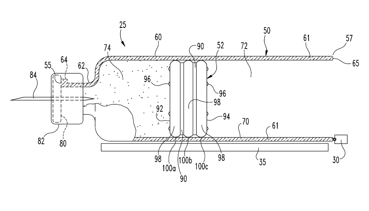
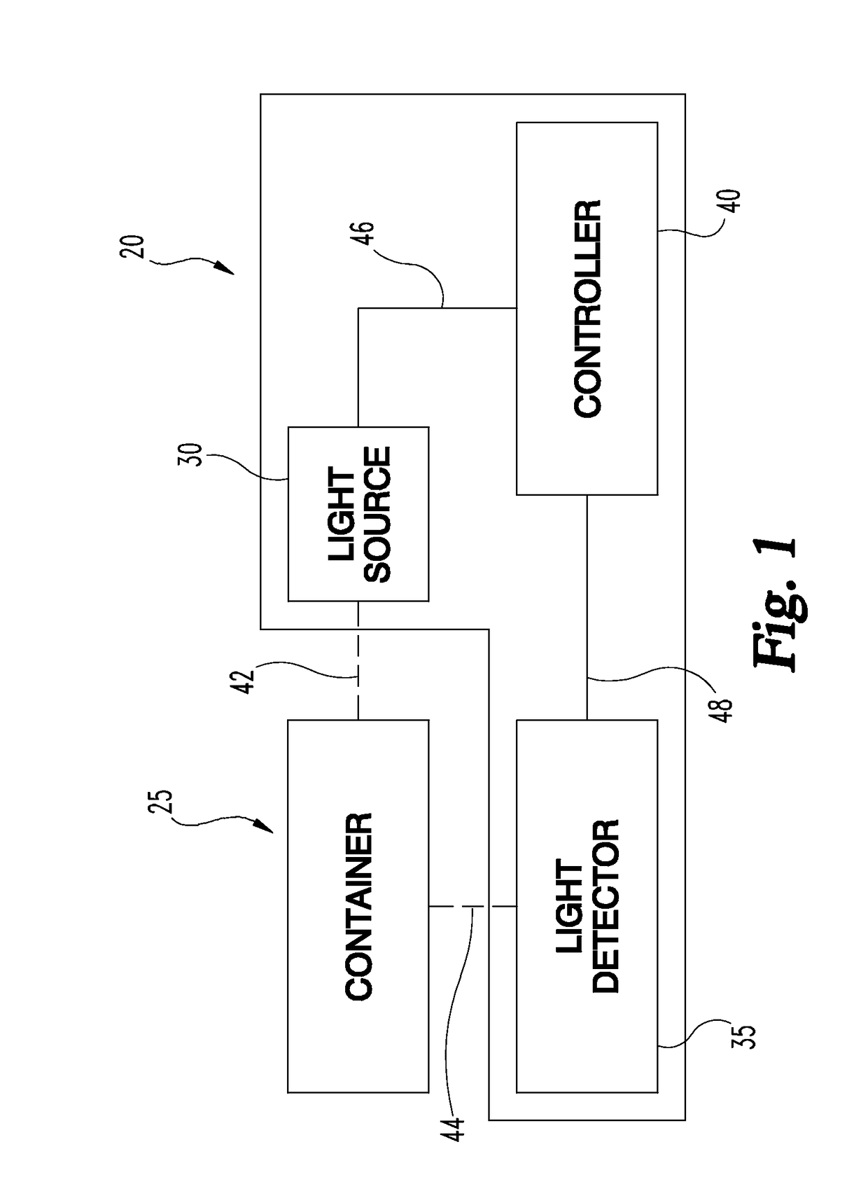
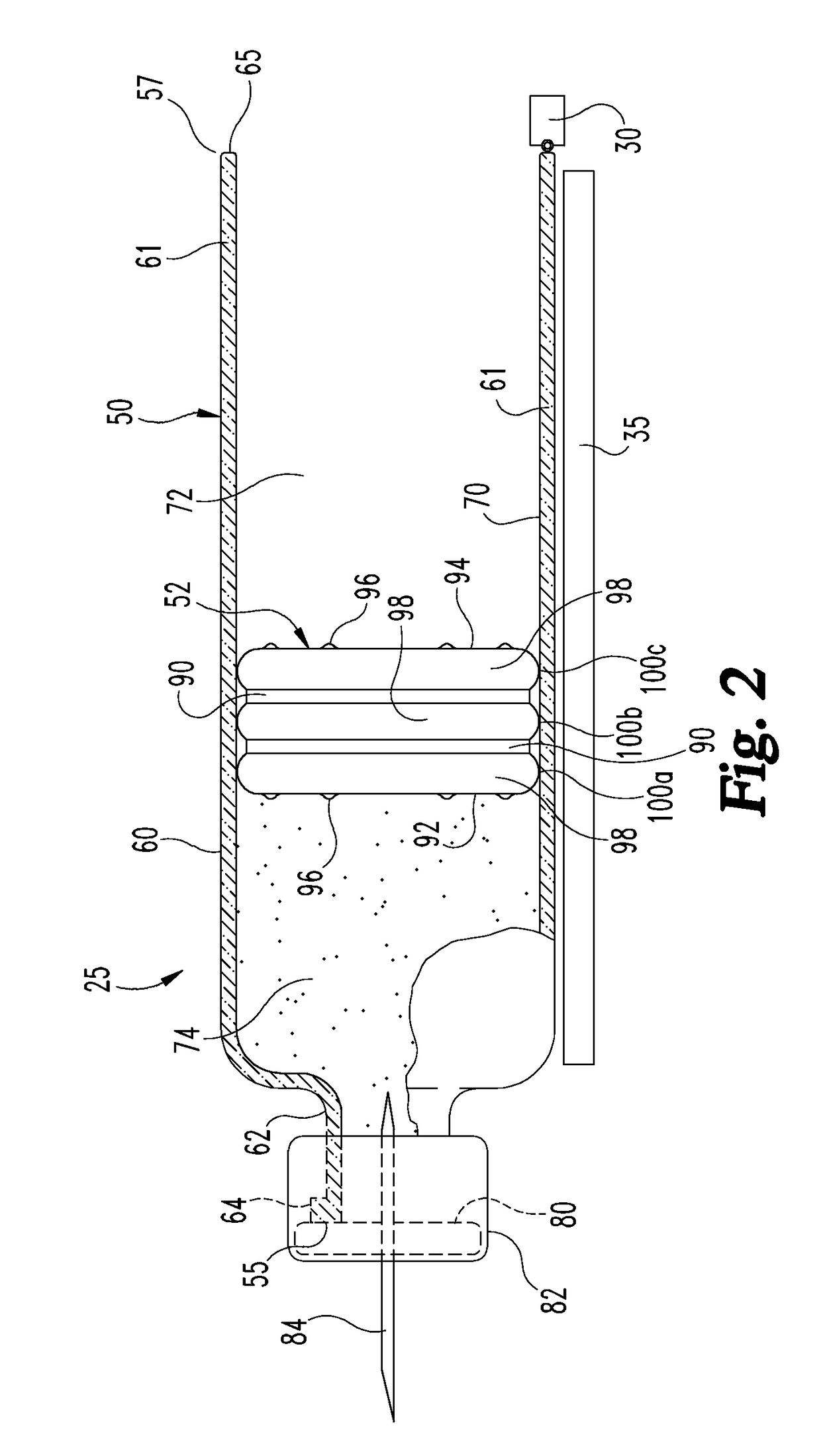
[0025]In FIG. 1, there is shown schematically a first embodiment of a sensing system of the present invention, generally designated 20, being used with a container generally indicated at 25. Sensing system 20 includes a light source 30, a light detector 35 and a controller 40. Light source 30 is positioned to operatively interact with container 25 by providing a light into the container wall as indicated at dashed line 42. Light detector 35 is positioned to operatively interact with container 25 by detecting light reflected from the container as indicated at dashed line 44. Controller 40 controls the operation of sensing system 20 and may be part of the overall control system of a device in which system 20 may be installed. Controller 40 uses data received from light detector 35 to determine information related to the container, such as the position of the plunger within the container which may be used to calculate fluid within the container, or changes in position of the plunger fo...


PUM


Abstract

A sensing system for determining a position of a plunger within a fluid container. The sensing system includes a light source, a light detector and a controller. The light source is configured to emit light into a barrel wall of the fluid container so that the barrel wall serves as a waveguide to guide the light to travel therein in an axial direction. The light detector is positioned to detect reflected light that was emitted by the light source, traveled through the barrel wall serving as the waveguide, and then reflected off a surface of the plunger. The controller is in communication with the light detector to determine an axial position of the plunger surface based on data from the light detector of the detected reflected light.

Description

BACKGROUND OF THE INVENTION[0001]The present invention pertains to fluid delivery devices, and, in particular, to a sensing system for determining the position of a plunger within a fluid container.[0002]A variety of known types of devices used to deliver fluid medication to a patient utilize medication-filled containers having movable plungers, such containers including cartridges and syringes. These types of devices include, but are not limited to, infusion pumps such as insulin pumps and medication injectors such as injection pens. A medication cartridge includes a movable plunger that seals medication within a barrel of the cartridge forward of the plunger. The cartridge plunger, when advanced by a drive mechanism of the delivery device in which the cartridge may be installed, forces medication from the cartridge through an outlet of that cartridge for delivery to a user.[0003]Knowing the axial position of a plunger within a container allows for various types of information to p...

Claims


Application Information

Patent Timeline
Patent Type & Authority Applications(United States)
IPC IPC(8): A61M5/315A61M5/31
CPCA61M5/31568A61M5/3129A61M2005/3126A61M2205/3389A61M2205/587A61M2205/3306A61M5/1452A61M5/1684A61M5/20
Inventor FORLANI, CHRISTIAN FABIOMASSARI, ROSSANO CLAUDIOMOJARRAD, MEHRAN
Owner ELI LILLY & CO
Why Eureka
Try Eureka