Robot system

a robot and robot technology, applied in the field of robot systems, can solve problems such as space was

Inactive Publication Date: 2010-11-18
YASKAWA DENKI KK
View PDF15 Cites 67 Cited by
  • Summary
  • Abstract
  • Description
  • Claims
  • Application Information

AI Technical Summary

Benefits of technology

[0010]By using this technique, the movement range of a robot can be limited without depending on a safety barrier or the like, or a safety barrier may be disposed so as to encircle a smaller region. Therefore, the limited floor space of a factory or the like can be efficiently used.

Problems solved by technology

For a robot having a small movement range, such as a robot for transporting small components, disposing a safety barrier outside the maximum movement range of the robot increases the space occupied by the robot and results in a waste of space.

Method used


Image

  • Robot system
  • Robot system
  • Robot system

Examples


first embodiment

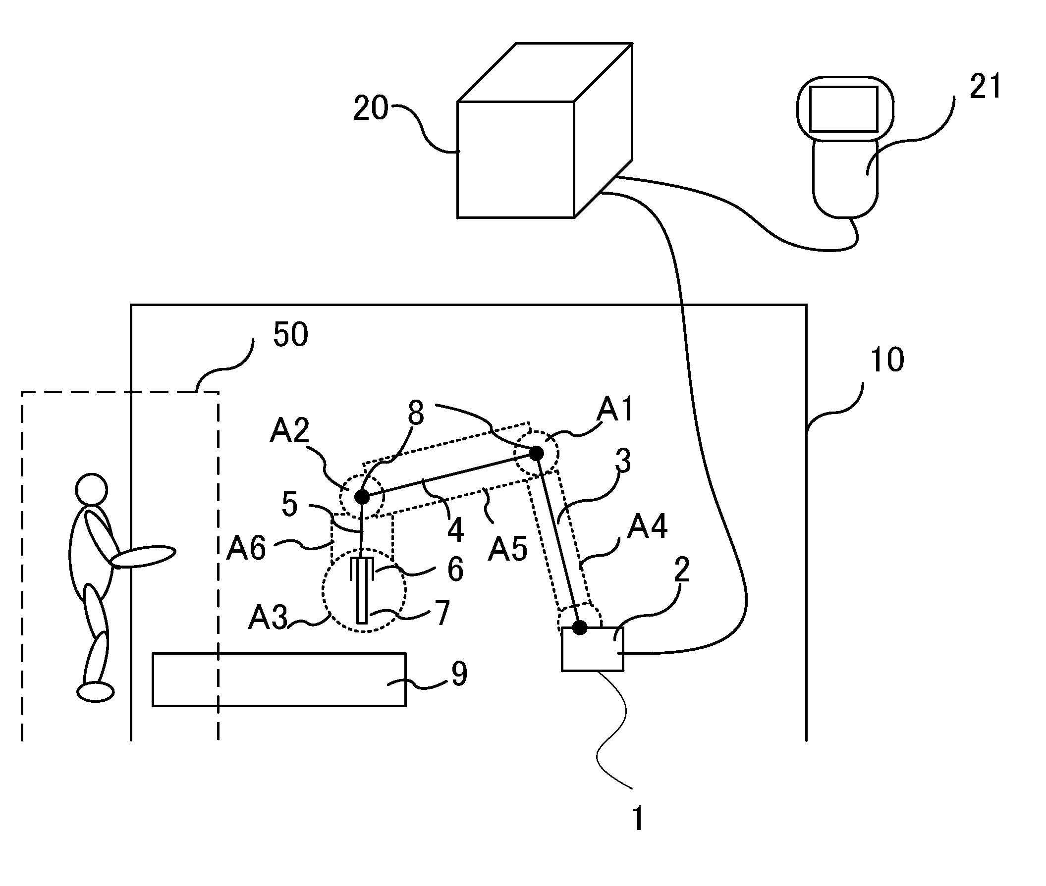
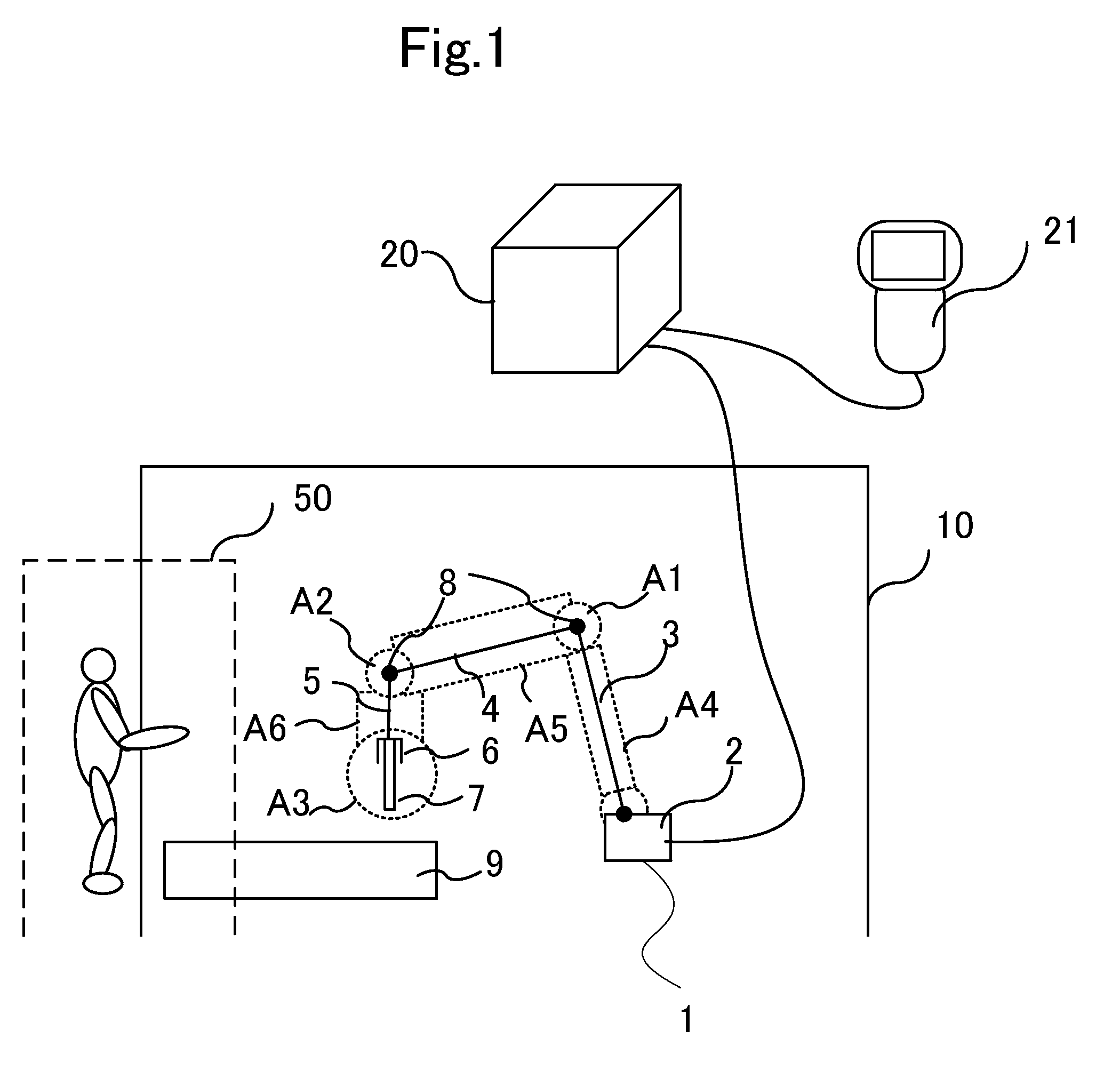
[0023]FIG. 1 is a diagram illustrating a method for limiting movement of a robot and a robot system that uses the method according to the present invention. A physical safety barrier 10 is disposed on a floor of a factory, and a robot 1 is disposed in the physical safety barrier 10.

[0024]In this example, the robot 1 includes a body 2 and three arms 3, 4, and 5. A tool 7 is attached to the arm 5 with a holding mechanism 6 therebetween. Examples of the tool 7 include a welding torch used for arc welding, a welding gun used for spot welding, and a hand for transporting an object. The arms 3, 4, and 5 are connected to each other through joints 8.

[0025]A workpiece 9 is placed on the floor. Examples of the workpiece 9 include an object to be welded and an object to be transported.

[0026]A controller 20 sends a necessary signal to the body 2. The arms 3, 4, and 5 move in a predetermined manner in accordance with a predetermined operation program. The holding mechanism 6 or the tool 7 moves ...

second embodiment

[0083]The method of limiting movement of a robot described above is implemented in a control program for controlling a robot. Alternatively, in order to increase safety and reliability, a control apparatus may be independently provided so that the control apparatus monitors whether a robot enters a movement-forbidden region and stops movement of the robot if the robot will enter the movement-forbidden region.

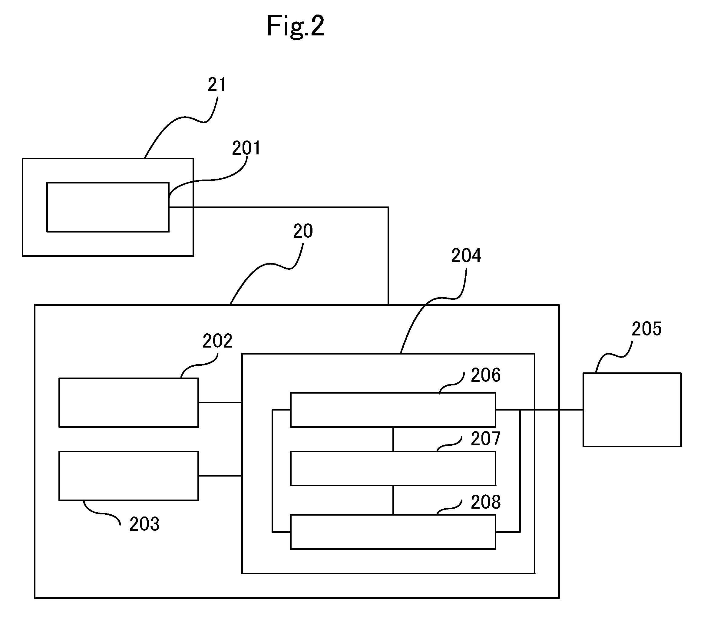
[0084]FIGS. 6 and 7 illustrate another embodiment of the present invention, which is an independent apparatus that performs such monitoring and stop control.

[0085]FIG. 6 illustrates a system in which a movement region monitoring device 601 is added to the system illustrated in FIG. 2. In the movement region monitoring device 601, a present position detection unit 602 reads a motor position 605 of each axis, which is detected by a position detector such as an encoder, from the drive unit 205 for each predetermined monitoring period. From the motor position 605 of each axis, the p...


PUM


Abstract

A robot system includes a robot and a robot controller including a drive unit, a memory that stores an arm-occupied region and a movement-forbidden region, a target position calculation unit that outputs a target position of a tool or a workpiece, a movement-forbidden region entry monitoring unit that checks whether the arm-occupied region based on the target position enters the movement-forbidden region and outputs a stop request if it is checked that the arm-occupied region enters the movement-forbidden region, and a predicted-coasting-position calculating unit that calculates a predicted coasting position of each axis and a coasting position of the tool or the workpiece in the case that the robot is urgently stopped. The movement-forbidden region entry monitoring unit checks whether the arm-occupied region at the coasting position enters the movement-forbidden region and outputs another stop request if it is checked that the arm-occupied region enters the movement-forbidden region.

Description

CROSS-REFERENCE TO RELATED APPLICATIONS[0001]The present application is a continuation application of PCT / JP2008 / 70770, filed Nov. 14, 2008, which claims priority to Japanese Patent Application No. 2007-316501, filed Dec. 7, 2007. The contents of these applications are incorporated herein by reference in their entirety.BACKGROUND OF THE INVENTION[0002]1. Field of the Invention[0003]The present invention relates to a robot system that includes an apparatus for limiting movement of a robot.[0004]2. Discussion of the Background[0005]Robots, in particular, industrial robots are widely used, for example, in automobile assembly factories and the like.[0006]When such a robot moves, an operation program (in which a set of instructions for making the robot perform an operation is described), which has been recorded in a memory of a controller, controls movement of a robot arm and a wrist (and a workpiece and a tool attached to the wrist) so as to move the robot arm and the wrist along a desi...

Claims


Application Information

Patent Timeline
Patent Type & Authority Applications(United States)
IPC IPC(8): B25J9/00G06F19/00G05B19/04G05B15/02
CPCG05B2219/39098B25J9/1676G05B2219/40203A61B19/2203A61B34/30
Inventor KARIYAZAKI, HIROKAZUMAEHARA, SHINICHIYAMAMOTO, MINORUTANAKA, MICHIHARU
Owner YASKAWA DENKI KK
Why Eureka
Try Eureka