
Engine power extraction control system

a control system and engine technology, applied in the direction of electric generator control, reciprocating combination engine, engine/propulsion engine ignition, etc., can solve the problems of high shaft power extraction demand, increase both fuel burn rate and residual thrust of the engine, and may suffer certain drawbacks of the architecture, so as to improve the overall engine operability, improve the surge margin of the propulsion engine compressor, and improve the effect of high power extraction demand

Active Publication Date: 2006-03-02
HONEYWELL INT INC
View PDF29 Cites 122 Cited by
  • Summary
  • Abstract
  • Description
  • Claims
  • Application Information

AI Technical Summary

Benefits of technology

[0006] The present invention provides a system and method for a more electric aircraft architecture that improves the surge margin of the propulsion engine compressors and improves overall engine operability during high power extraction demands.

Problems solved by technology

Although these architectures are generally safe, robust, and reliable, the architectures may suffer certain drawbacks.
For example, high shaft power extraction demand can negatively impact compressor surge margin.
This solution, however, can increase both the fuel burn rate and the residual thrust that the engine generates, most notably during flight and ground idle conditions and during transients.

Method used


Image

  • Engine power extraction control system
  • Engine power extraction control system
  • Engine power extraction control system

Examples


Embodiment Construction

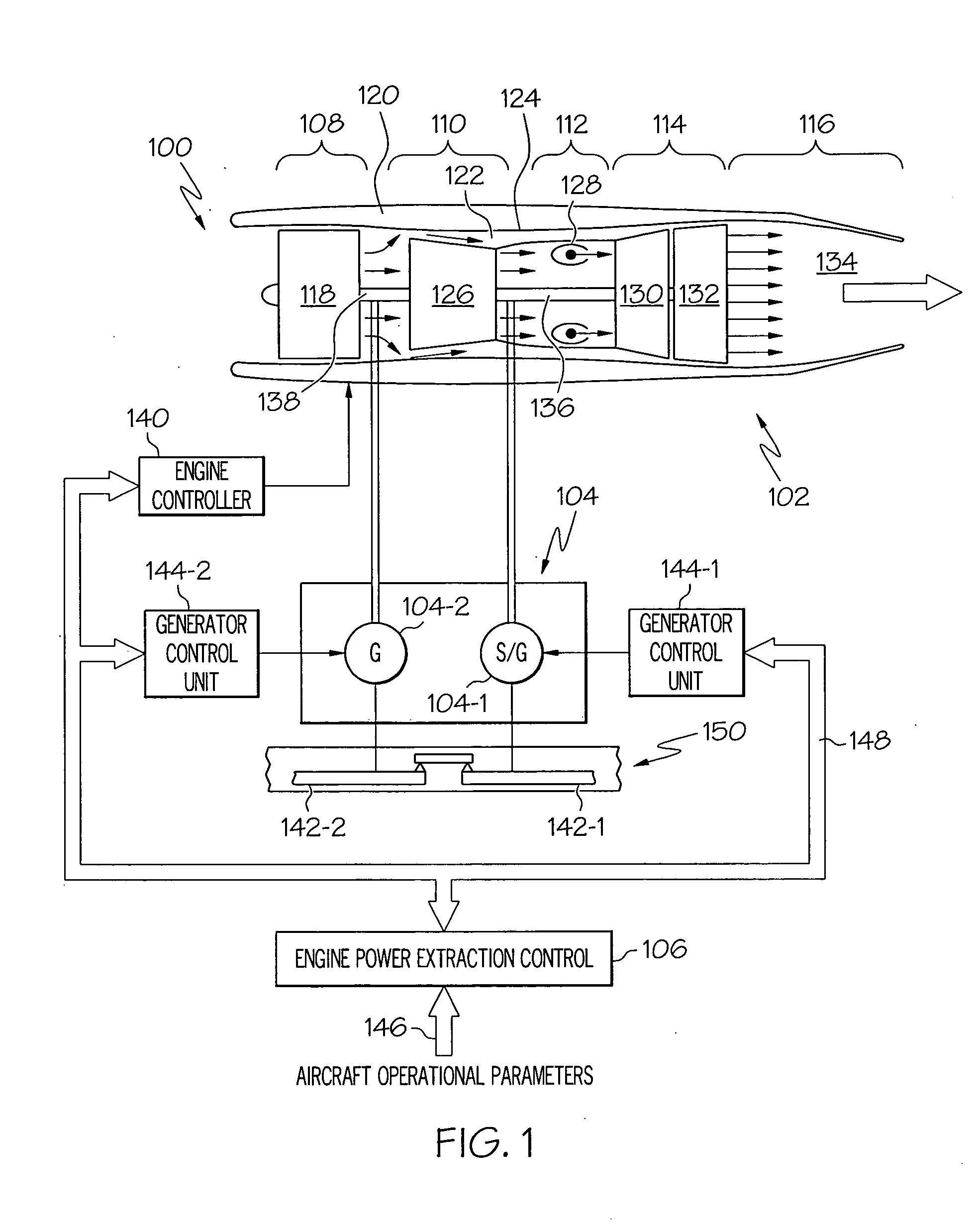
[0013] Before proceeding with a detailed description, it is to be appreciated that the described embodiment is not limited to use in conjunction with a particular type of turbine engine. Thus, although the present embodiment is, for convenience of explanation, depicted and described as being implemented in combination with a multi-spool turbofan gas turbine jet engine, it will be appreciated that it can be implemented in various other types of turbines, and in various other systems and environments.

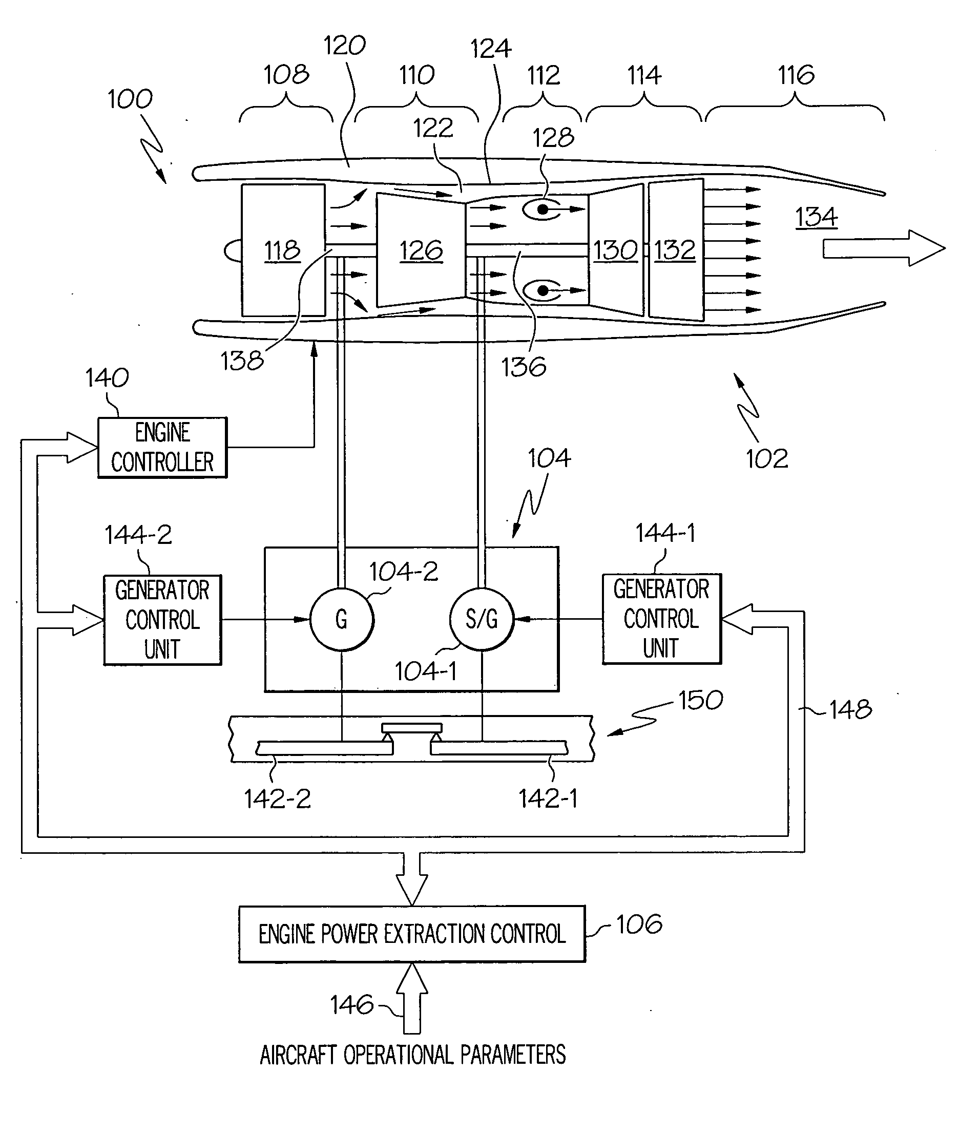
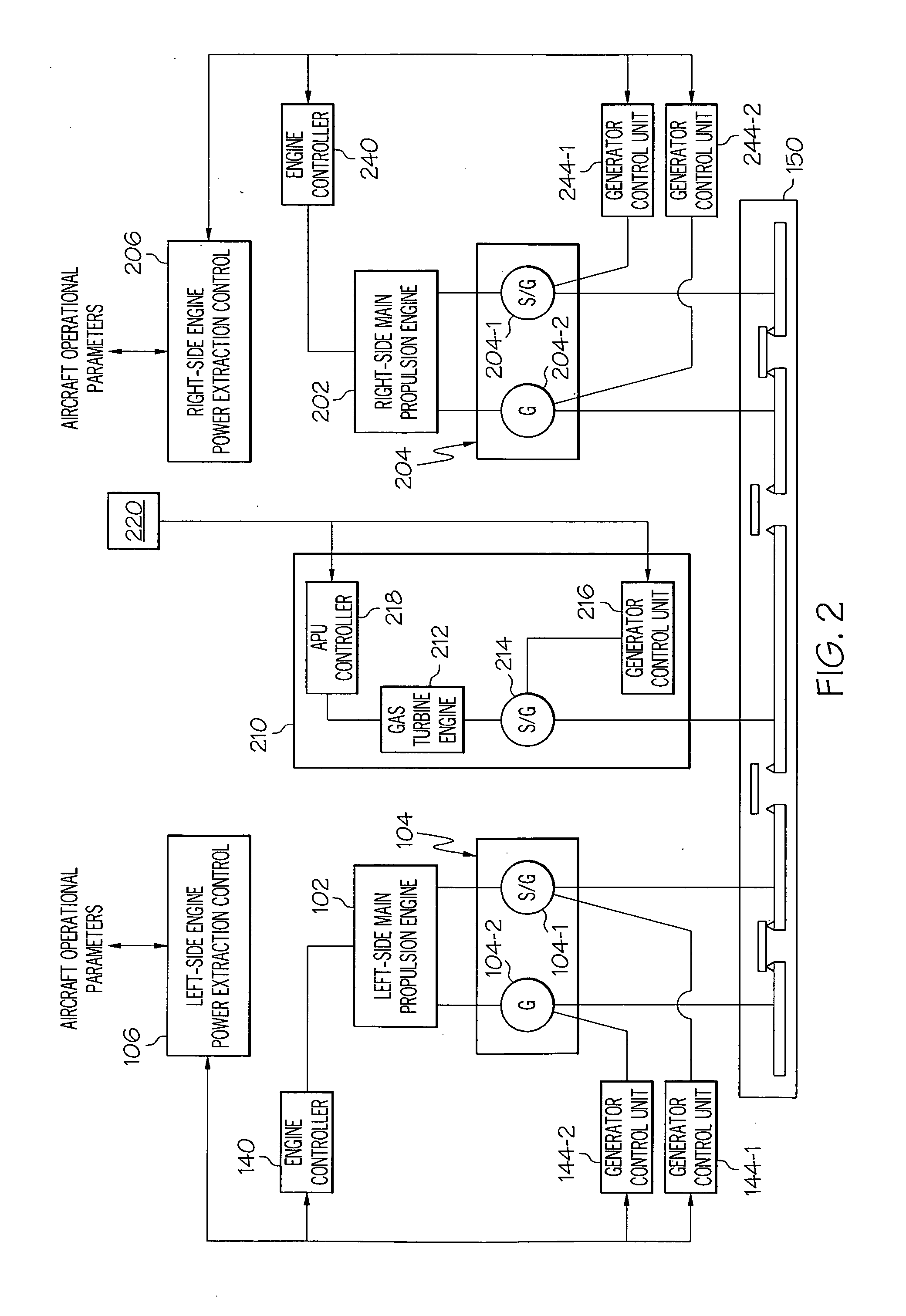
[0014] Turning now to FIG. 1, an embodiment of an exemplary engine power extraction system 100 is shown in schematic form. The system 100 includes a main propulsion engine 102, a plurality of electrical machines 104 (e.g., 104-1, 104-2), and an engine power extraction control circuit 106. In the depicted embodiment, the main propulsion engine 102 is a multi-spool turbofan gas turbine jet engine, and includes an intake section 108, a compressor section 110, a combustion section 112, a tur...


PUM


Abstract

An engine power extraction control system controls the main propulsion engines and the electrical machines that are coupled thereto to supply an appropriate amount of aircraft thrust and electrical energy to the aircraft. The engines and electrical machines are also controlled so that the propulsion thrust that is generated is split between the various turbines in the main propulsion engines to maintain an adequate surge margin and to minimize residual thrust generation.

Description

CROSS-REFERENCES TO RELATED APPLICATIONS [0001] This application claims the benefit of U.S. Provisional Application No. 60 / 604,611, filed Aug. 25, 2004.TECHNICAL FIELD [0002] The present invention relates to engine power control and, more particularly, to a system and method of controller engine thrust generation by, and power extraction from, an aircraft main propulsion engine. BACKGROUND [0003] Aircraft main propulsion engines not only generate propulsion thrust for the aircraft, but in many instances may also be used to drive various other rotating components such as, for example, generators, compressors, and pumps, to thereby supply electrical, pneumatic, and / or hydraulic power. In multi-spool turbofan gas turbine engines, this is accomplished via a plurality of turbines. In particular, each turbine receives a flow of combusted gas from a combustor and, in response, generates shaft power that is used to drive one or more of these rotational components, via a plurality of concent...

Claims


Application Information

Patent Timeline
Patent Type & Authority Applications(United States)
IPC IPC(8): F02C7/268
CPCF02C9/26F05D2220/76F05D2270/05
Inventor DEROUINEAU, JEAN-LUC
Owner HONEYWELL INT INC
Learn More