
Super high speed multi-hull watercraft

a multi-hull, super high-speed technology, applied in special-purpose vessels, vessel construction, transportation and packaging, etc., can solve the problem that the velocity of wind entering the m-hull craft tends to destroy the bow wave spiral, and achieve the effect of maximizing the volume and velocity of incoming air, maximizing the dynamic lift from the impact of entering air, and maximizing the volume and velocity of air

Inactive Publication Date: 2006-08-22
M SHIP
View PDF17 Cites 12 Cited by
  • Summary
  • Abstract
  • Description
  • Claims
  • Application Information

AI Technical Summary

Benefits of technology

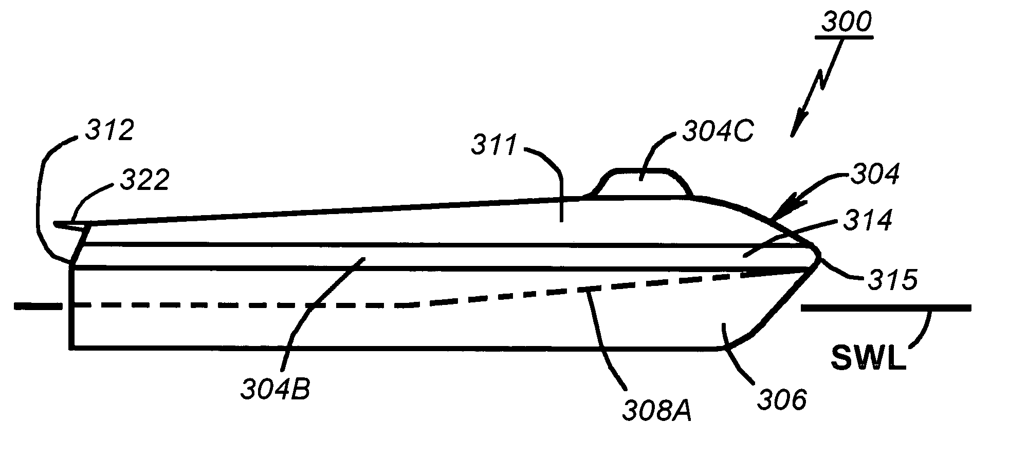
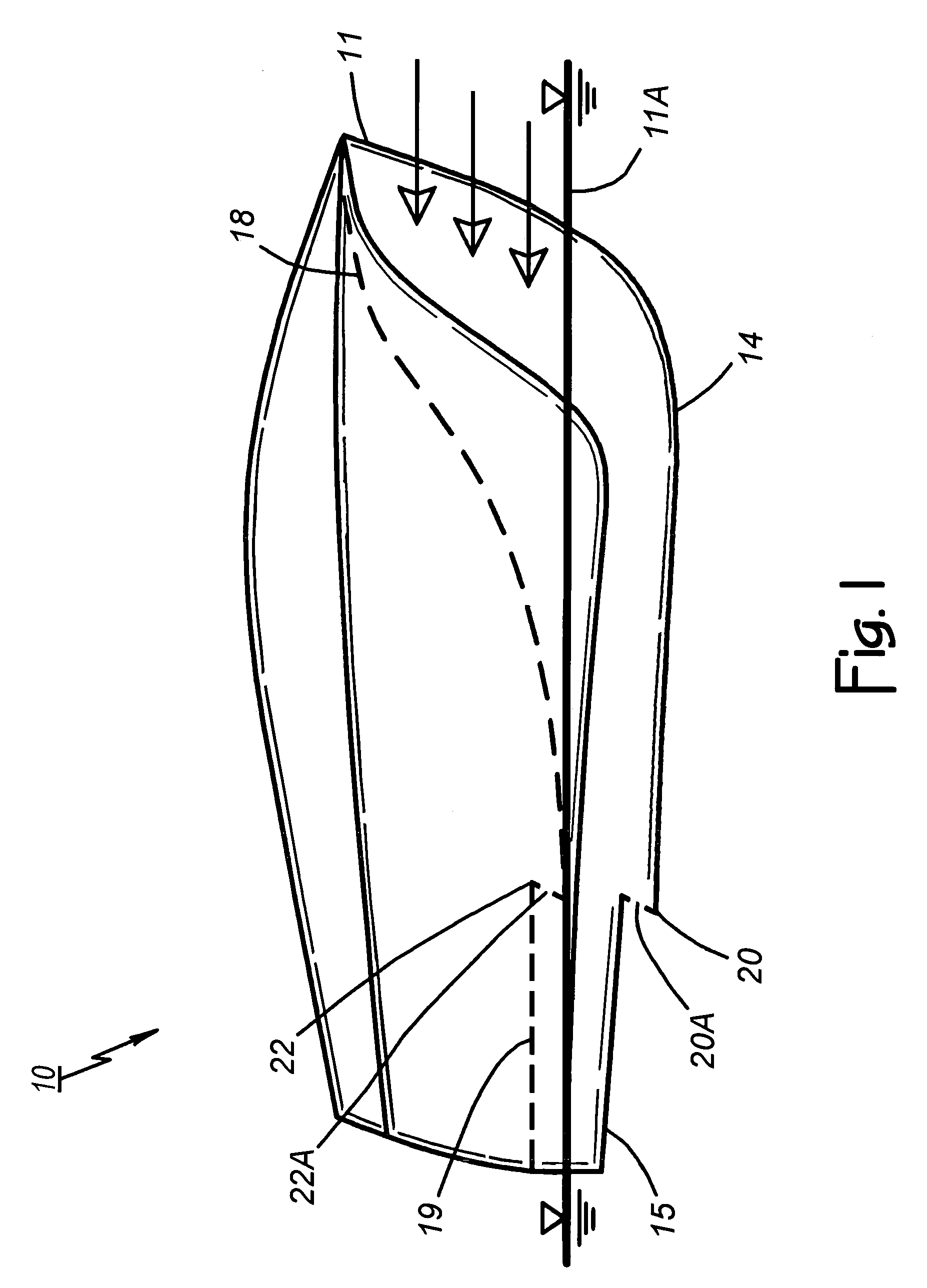
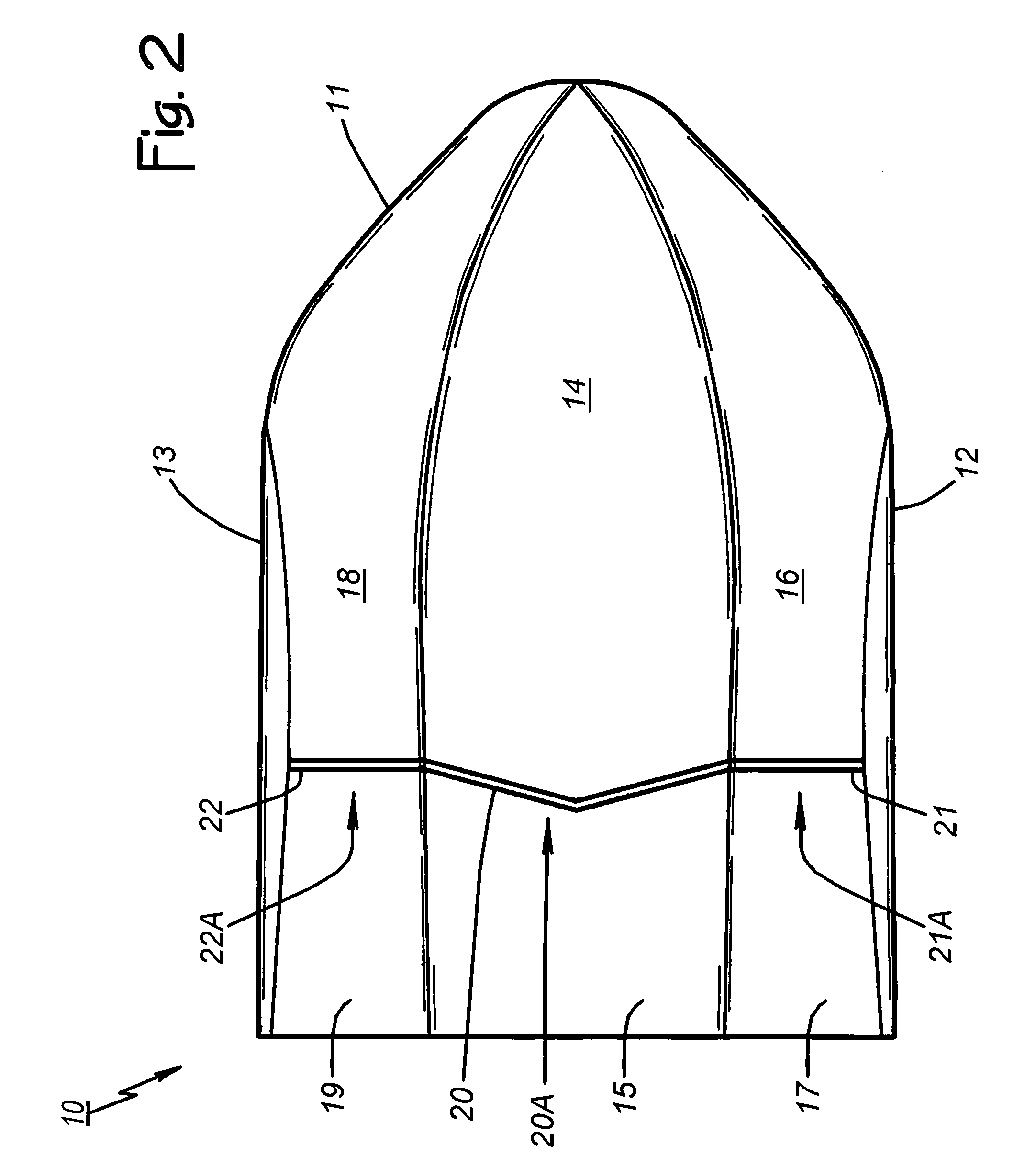
[0009]This invention addresses the need outlined above by providing a watercraft having a wing-like deck structure atop multiple hulls, together with downwardly extending vertical skirts and planing tunnels similar to the bow-wave-capturing skirts and planing tunnels of an M-shaped hull. The resulting super high speed watercraft includes wider planing tunnels that eliminate dependence on the bow wave spiral for the lift associated with increased pressure in the planing tunnels. The deck structure includes an airfoil-like upwardly facing surface that adds the aerodynamic lift associated with decreased pressure over the deck. These elements combine to form what may be called a “floating wing” that is capable of performing at speeds well over fifty knots.
[0012]Preferably, planing tunnel width is greater than that of existing M-shaped watercraft and the slope of the planing tunnel ceiling is designed to maximize the volume and velocity of incoming air in order to thereby maximize the dynamic lift from the impact of entering air. In other words, the bow structure is designed to maximize the volume and velocity of air entering the planing tunnels and eliminate the dependence on the bow wave spiral for air compression. Preferably, the watercraft includes an enhanced propulsion system and planing lift from engine exhaust as described in U.S. patent application Ser. No. 10 / 957,914 filed Oct. 4, 2004 by the inventors of this patent application. One embodiment includes hinged laterally extending deck extensions that an operator can raise to reduce vessel breadth during docking, upwardly extending barriers on the deck extensions that reduce the escape of wind over the deck structure laterally, and hinged flap structures disposed rearwardly that enable an operator to adjust vessel trim.
[0013]Thus, the invention, in all its variations referred to as a “floating wing,” significantly increases the speed capabilities of the M-hull with the structural improvements outlined above. Aerodynamic lift over the deck and dynamic lift from compressed air entering the planing tunnels, combine with enhanced propulsion and engine exhaust lift to enable super high-speed operation for military and other uses.

Problems solved by technology

For super high speeds in the range of fifty to one hundred knots, however, the volume and velocity of wind entering the M-hull craft tends to destroy the bow wave spiral, with the incoming wind replacing the bow wave spiral as the means of forcing air aft under increasing pressure.

Method used


Image

  • Super high speed multi-hull watercraft
  • Super high speed multi-hull watercraft
  • Super high speed multi-hull watercraft

Examples


Embodiment Construction

[0034]The description of the preferred embodiment begins with a Powered Watercraft With M-Shaped Hull introductory section of this specification that restates some information presented in U.S. patent application Ser. No. 10 / 625,135 filed Jul. 23, 2003 by the inventors of this patent application (now U.S. Pat. No. 6,868,798 issued Mar. 22, 2005). That background section makes reference to FIGS. 1–9 in describing watercraft having one or more planing surfaces and one or more steps in the planing surfaces at which exhaust is vented.

[0035]Next, information is presented in an Exhaust Proportioning System section of this specification that restates some information presented in U.S. patent application Ser. No. 10 / 957,914 filed Oct. 4, 2004 by the inventors of this patent application. That background section makes reference to FIGS. 10–13 in describing a watercraft having a dual exhaust system with means for controlling the proportions of exhaust vented at steps in the planing surfaces an...


PUM


Abstract

A watercraft with at least one onboard propulsion engine includes at least two hulls and a wing-like deck structure spanning the two hulls (a floating wing). Port and starboard skirts combine with the deck structure to form port and starboard planing channels. The deck structure includes an upwardly facing surface that slopes downwardly toward an aft end of the deck structure in order to provide aerodynamic lift. Preferably, a speed-responsive exhaust proportioning system vents exhaust at vertical steps in planing surfaces on the hulls to reduce drag, increase lift, and reduce thermal signature. One embodiment includes hinged laterally extending deck extensions that an operator can raise to reduce vessel breadth during docking, upwardly extending barriers on the deck extensions that reduce the escape of wind laterally, and hinged flap structures disposed rearwardly that enable an operator to adjust vessel trim.

Description

CROSS REFERENCE TO RELATED APPLICATIONS[0001]This application is a continuation in part of commonly assigned U.S. patent application Ser. No. 10 / 957,914 filed Oct. 4, 2004 (the parent application that issued as U.S. Pat. No. 6,983,713 B1 on Jan. 10, 2006), which parent application is a continuation in part of commonly assigned U.S. patent application Ser. No. 10 / 625,135 filed Jul. 23, 2003 (the grandparent application that issued as U.S. Pat. No. 6,868,798 B2 on Mar. 22, 2005).BACKGROUND OF THE INVENTION[0002]1. Technical Field[0003]This invention relates generally to powered watercraft, and more particularly to a super high speed watercraft having multiple M-shaped hulls and bow structure that enable performance at over fifty knots.[0004]2. Description of Related Art[0005]The term “M-shaped hull” as used herein refers to a boat hull falling within the scope of one or more claims of U.S. Pat. Nos. 6,250,245; 6,314,903; and 6,526,903. “M-hull craft” and “M craft” are watercraft that ...

Claims


Application Information

Patent Timeline
Patent Type & Authority Patents(United States)
IPC IPC(8): B63B1/32
CPCB63B1/20B63B1/322B63B1/38B63B2001/202Y02T70/122B63B2001/207B63B2001/208B63B2001/385Y02T70/12B63B2001/206Y02T70/10
Inventor ROBINSON, CHARLES W.BURNS, III, WILLIAM F.
Owner M SHIP
Learn More