Plasma ignition for direct injected internal combustion engines

a technology of internal combustion engine and ignition, which is applied in the direction of engine starters, combustion-air/fuel-air treatment, sparking plugs, etc., can solve the problems of long actual time (not cranking, rotation) that it takes for fuel and air to mix and burn, and the pollution of diesel engines, so as to improve engine durability, reduce nox emissions, and enhance engine life

Inactive Publication Date: 2005-04-26
JAYNE MICHAEL E
View PDF1 Cites 53 Cited by
  • Summary
  • Abstract
  • Description
  • Claims
  • Application Information

AI Technical Summary

Benefits of technology

[0050]Another object of the present invention is to enhance engine life for reciprocating internal combustion engines. Greater engine durability is the result of lower NOx emissions and lower peak pressures inside the combustion chamber. When NOx is created during the combustion process, this NOx reacts with the water naturally created by the combustion to create nitric acid. This nitric acid accelerates engine wear, but if nitric acid production during the combustion process is greatly reduced, engine durability is enhanced. Reducing the peak pressure within the combustion chamber during the power stroke has the effect of lowering the peak loads upon the engine bearings, further enhancing durability of the engine.
[0051]It is a further object of the present invention to make it possible to retrofit existing reciprocating direct injected internal combustion engines with the present invention at a minimum of expense and time. The present invention can be installed on most diesel engines in current use by removal of the cylinder head, installing injector / igniter assemblies on that cylinder head, reinstalling the modified original cylinder head, and then installing the electronics that go with it. In most cases it will not be necessary to either remove the entire engine from where it has been installed or completely replace the existing cylinder head. The importance of this retrofit application of the present invention to reciprocating 2-cycle and 4-cycle diesel engines cannot be overstated. The environmental and economic benefits made possible by the present invention are expanded dramatically as a result of it being possible to retrofit existing engines. Reciprocating internal combustion engines retrofitted with the present invention should benefit from all of the advantages that are possible, with the exception of engine weight reduction.
[0052]It is also another object of present invention to make it possible to design diesel fueled reciprocating internal combustion engines that weigh less for a given power output. Engine weight in new diesel engines designed and produced with the present invention incorporated into them can be designed to weigh much less for a given power output.
[0053]This is possible as a result of the lower peak combustion chamber pressures that occur in a reciprocating direct injected internal combustion engine, such as a diesel engine, that has the present invention incorporated into it. Diesel engines currently being manufactured have to be designed to deal with very high peak pressures inside of the combustion chamber that are necessary for heat-of-compression ignition to work. These very high peak pressures are also responsible for the creation of NOx. Because lower peak pressures inside the combustion chamber will occur in a diesel engine equipped with the present invention, the engine block will be subjected to lower peak stresses making it possible to design the engine to weigh less for a given engine displacement and power output.

Problems solved by technology

The primary cause of diesel engine pollution is its dependence upon the heat of compression inside the combustion chamber for initiation and maintenance of the combustion process.
Regardless of engine rpm, the actual time (not degrees of crank rotation) that it takes for the fuel and air to mix and burn is relatively long because diesel fuel is notoriously hard to ignite and keep burning.
This results in a very high combustion chamber pressure even before the fuel is injected into the combustion chamber.
Pollution from these oxides of nitrogen is the primary cause of acid rain, photo-chemical smog and a host of other very serious ecological and health problems.
The actual time needed for complete combustion to take place in a diesel engine is the primary cause of the other main type of pollutant emissions from diesel engine operation.
This problem becomes worse if the engine is operating at full speed (as measured in revolutions per minute) and / or at full power.
Making this pollution even worse is the fact that the NOx created reacts with the water naturally present in engine exhaust to make nitric acid.
These chemicals are so harmful that under present Federal law, they could not be accepted by a landfill in the form of solid or liquid waste.
This was done for three reasons:1. Diesel engines get much better fuel economy than gasoline engines of the same power output;2. The currently accepted theory of operation for diesel engines did not allow for major changes in design that could be applied in a cost-effective manner; and3. There was not any readily available alternative type of engine design that could perform the jobs currently done by diesel engines.
Over the last three decades this has resulted in a slower pace of design advancement for diesel engines, especially for pollution reduction, when compared to design advancements made on gasoline engines.
However, air pollution created by diesel engines has remained about the same for a given amount of power produced.
This caused the relative percentage of air pollution produced by diesel engines to become the primary cause of air pollution in the US.
Although these systems may enhance combustion to some extent, the spark plug itself is only exposed to one specific point of the fuel-air mixture at any given time.
The application of heat to the fuel and to the combustion chamber may assist the combustion process, especially during cold starting, as shown by the use of glow plugs and fuel pre-heaters in diesel engines currently in production; but there is a drawback to the introduction of additional heat into the combustion process in that it will result in greater creation of oxides of nitrogen.
Another problem with this approach is the relative inefficiency of electrical resistance heating elements in terms of the power that they require, and their relatively short life in terms of total hours of operation after which they need to be replaced.

Method used


Image

  • Plasma ignition for direct injected internal combustion engines
  • Plasma ignition for direct injected internal combustion engines
  • Plasma ignition for direct injected internal combustion engines

Examples


Embodiment Construction

[0095]The invention will now be described in further detail in connection with illustrative preferred embodiments for improving combustion in a direct injected internal combustion engine enabling the engine to achieve better fuel economy, reduced pollutant emissions, and more power. Within the scope of the present invention, this system could be applied to gas turbines and to reciprocating internal combustion engines that are direct injected of either the 2-stroke or the 4-stroke type that have been designed for use with any type of combustible fuel including gasoline, diesel or jet fuel.

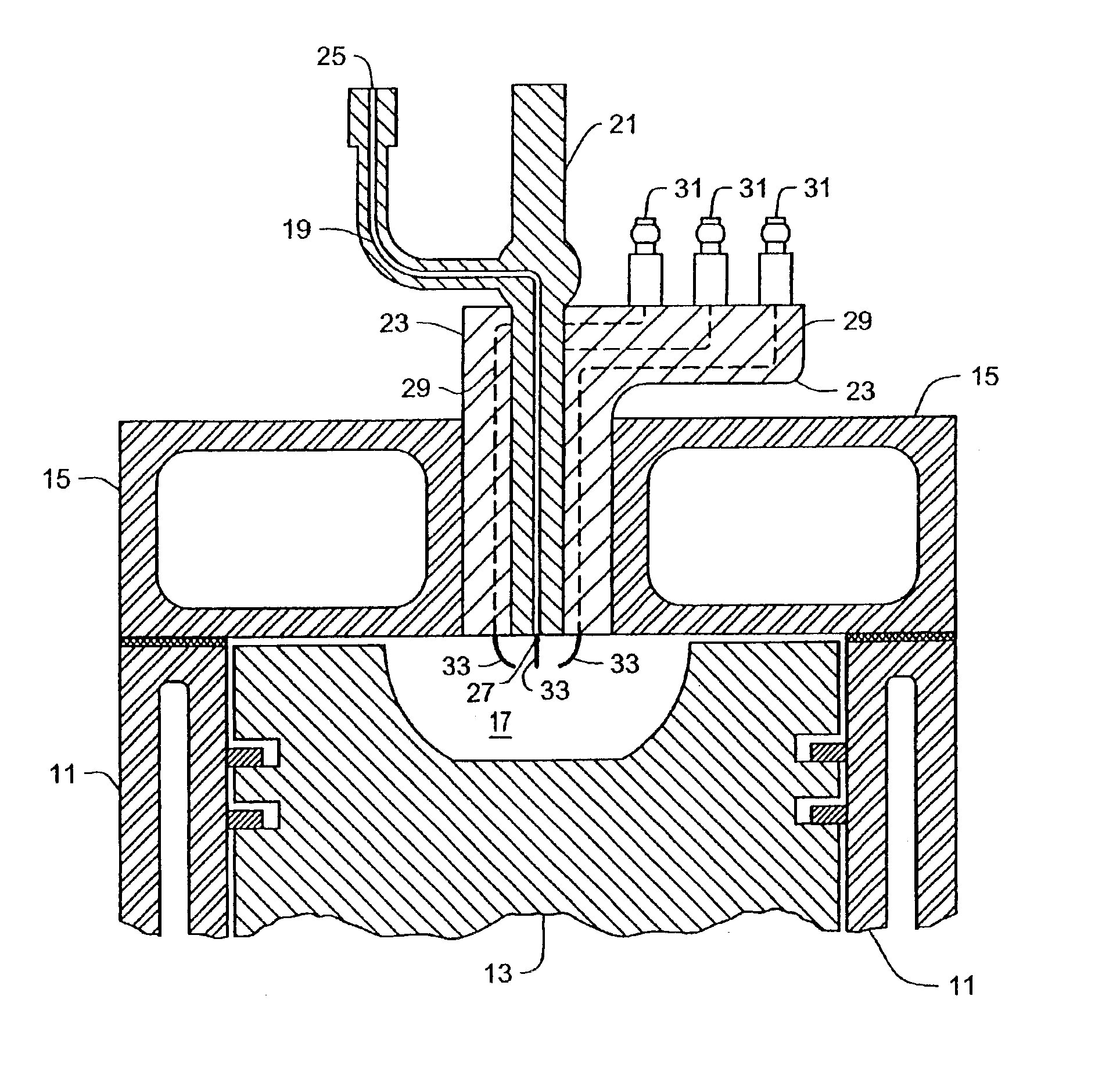
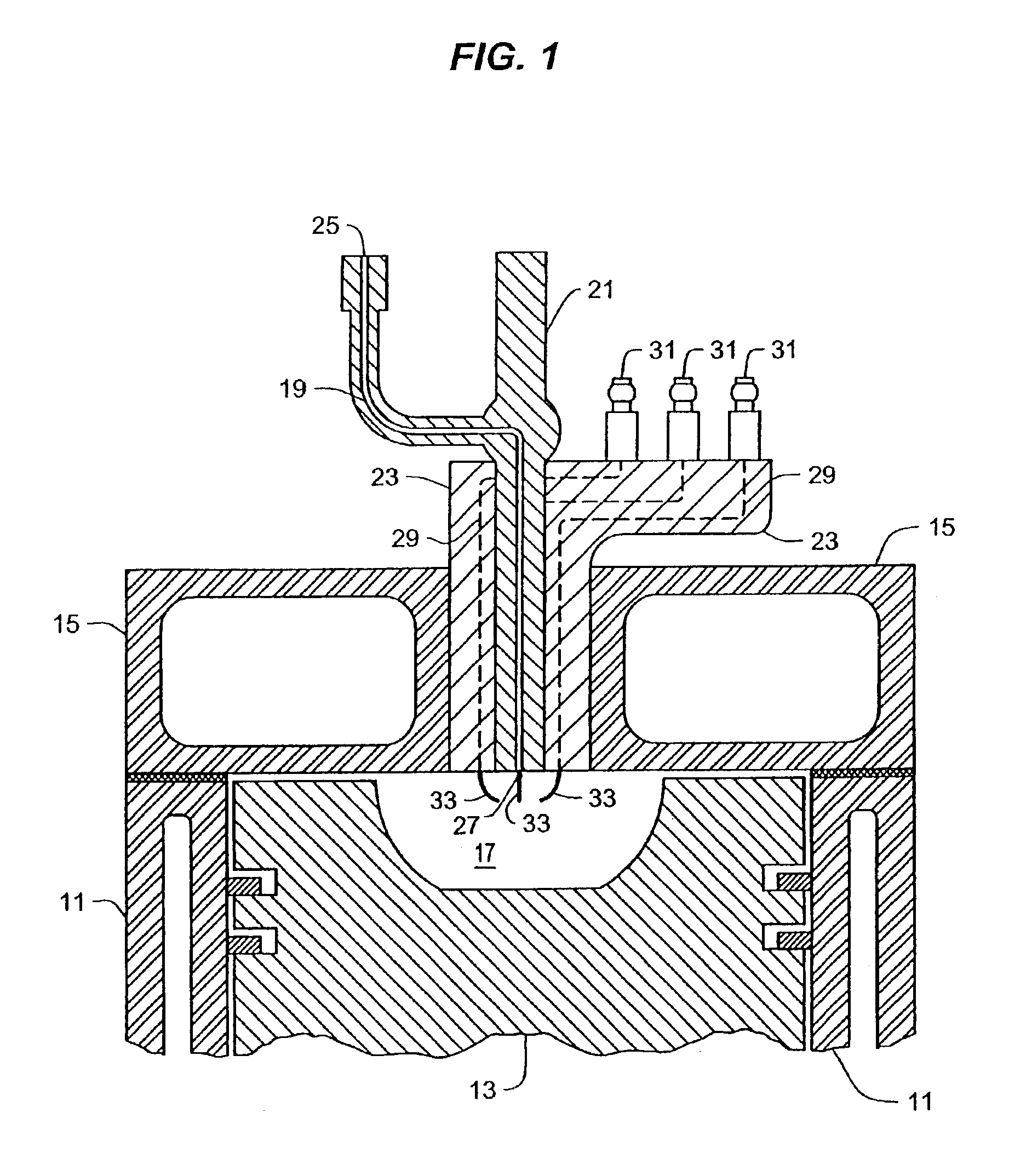
[0096]Referring to FIG. 1, the present invention is shown mounted in a cylinder head 15 of a diesel engine. An engine block 11 has placed inside it a piston 13 and mounted on top of the engine block 11 is the cylinder head 15. A combustion chamber 17 is located inside the area surrounded by the engine block 11, the piston 13, and the cylinder head 15. Passing through the cylinder head 15 is a fuel i...


PUM


Abstract

An apparatus and method for the creation, placement and control of an area of electrical ionization within an internal combustion engine combustion chamber. This area of electrical ionization is positioned so that all of the fuel being injected into the combustion chamber must pass next to or through the area of electrical ionization to ensure that combustion has been initiated for all of the fuel as it is injected. This area of electrical ionization can be kept on as long as it is necessary to insure that the all of the fuel that is injected into the combustion chamber can be completely combusted. An engine equipped with this electrical ionization device has its fuel economy enhanced by timely, controlled, and complete combustion of all of the fuel injected into its combustion chamber. Furthermore, the pollutant emissions of both oxides of nitrogen and unburned hydrocarbons are reduced dramatically. Further, cold starting capability of this engine is greatly enhanced by a major reduction in the time necessary for the engine to warm up and a major reduction of pollutants created by the engine during the warm-up period. Additionally, this method of combustion also allows the engine to operate at a higher speed (rpm) allowing an increase in peak power output.

Description

[0001]This new application is a continuation application of U.S. application Ser. No. 09 / 954,195 filed on Sep. 18, 2001, now abandoned, which is a continuation application of U.S. patent application Ser. No. 09 / 501,788 filed on Feb. 11, 2000, now U.S. Pat. No. 6,289,868 issued on Sep. 18, 2001.BACKGROUND OF THE INVENTION[0002]1. Field of the Invention[0003]The present invention relates to a method and apparatus for assuring combustion of fuel injected in a combustion chamber of an internal combustion engine.[0004]2. Description of the Related Art[0005]Diesel engines of both the 2-cycle and 4-cycle types have enormous acceptance throughout the world and they are also the types of engines that would benefit the most from application of the present invention. When engine longevity and fuel economy are more important than the power-to-weight ratio or the ability to operate through a wide range of engine speeds, diesel fueled engines are ideal.[0006]Both Sir Harry R. Ricardo in his book ...

Claims


Application Information

Patent Timeline
Patent Type & Authority Patents(United States)
IPC IPC(8): F02M57/06F02M57/00F02M27/00F02P3/12F02M27/04F02P3/00H01T13/00H01T13/50F02B23/10F02B75/12F02B75/00F02F3/26
CPCF02M27/042F02M57/00F02P3/12H01T13/50F02N15/023F02M57/06F02B23/101F02B2075/125F02F3/26F02N2015/061Y02T10/123Y02T10/12
Inventor JAYNE, MICHAEL E.
Owner JAYNE MICHAEL E
Why Eureka
Try Eureka