System and method for preparing an optimized fuel mixture

Inactive Publication Date: 2010-04-22
PLATA CARLOS A
View PDF9 Cites 4 Cited by
  • Summary
  • Abstract
  • Description
  • Claims
  • Application Information

AI Technical Summary

Benefits of technology

[0010]Through the system and method described above, the invention allows for the preparation of an optimized fuel mixture that significantly improves the performance

Problems solved by technology

Conventional internal combustion engines are notoriously inefficient and pollu

Method used


Image

  • System and method for preparing an optimized fuel mixture
  • System and method for preparing an optimized fuel mixture
  • System and method for preparing an optimized fuel mixture

Examples


Example

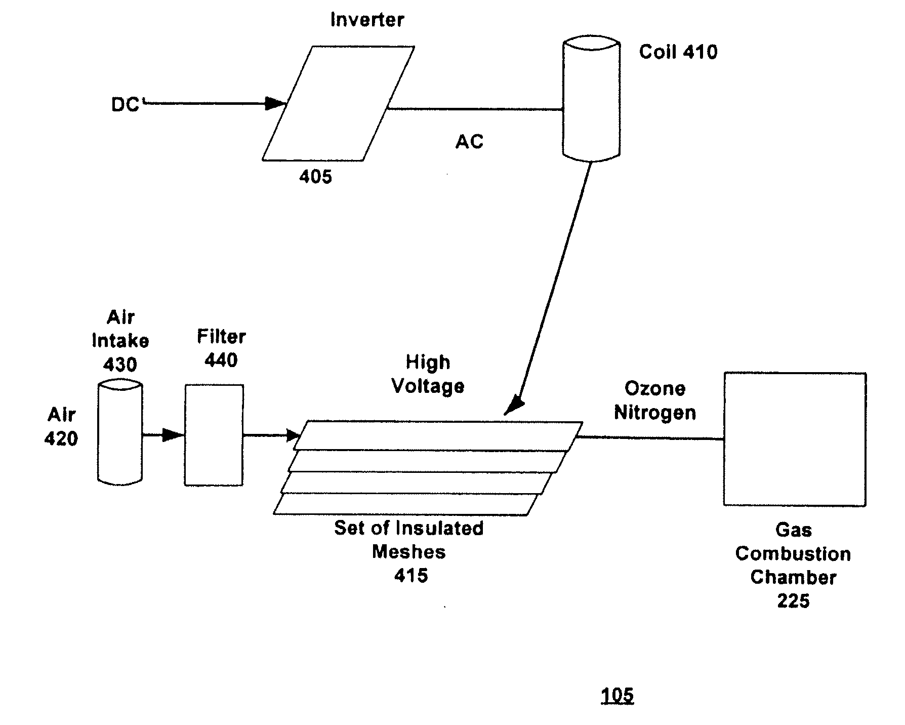
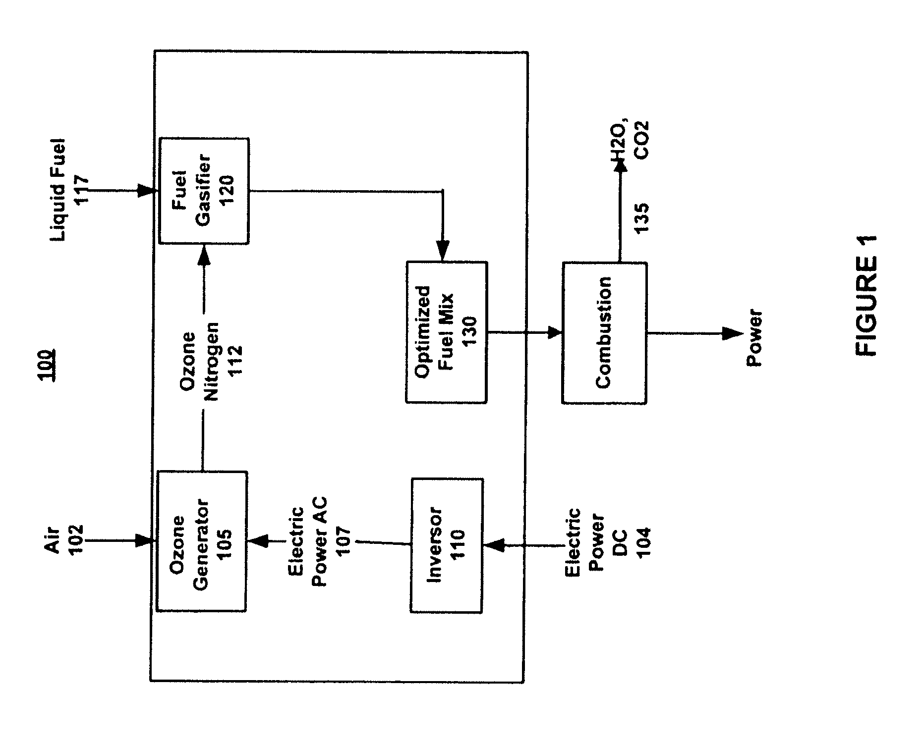
[0018]FIG. 1 shows a block diagram of a system 100 for optimizing a fuel combustion mix in accordance with the invention. FIG. 1 shows an ozone generator 105. The ozone generator 105 receives ambient air 102 from an intake (not shown in FIG. 1). As shown in FIG. 1, the ozone generator 105 includes an inversor 110 which receives DC current 104 and converts it to AC current 107 for use by the ozone generator 105. The operation of the ozone generator 105 is described in greater detail below in conjunction with FIG. 4 however, in general, the ozone generator 105 processes the ambient air 102 so as to yield ozone 112 (and / or an ozone nitrogen mixture). The ozone 112 is then fed into a fuel gasifier 120 also shown in FIG. 1.

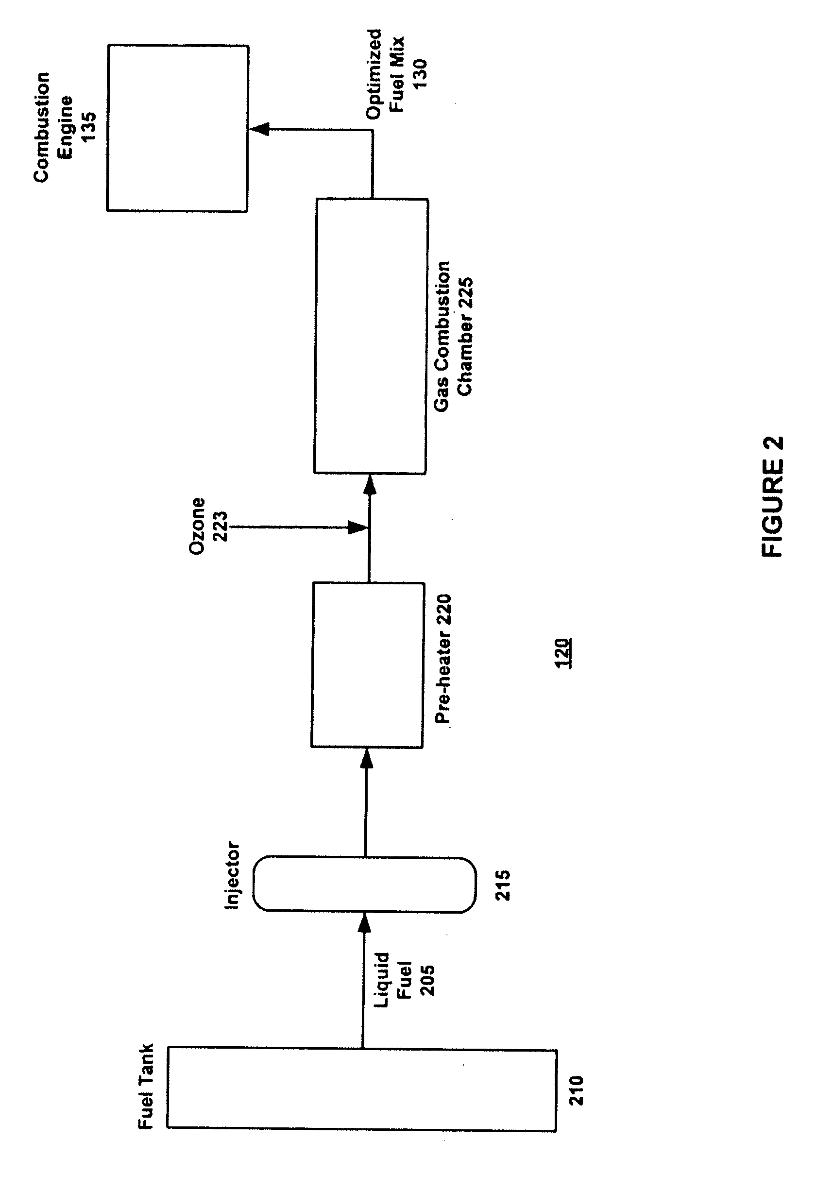
[0019]The fuel gasifier 120 receives liquid fuel 117, such as gasoline or any other combustible liquid fuel. The gasifier 120 also receives the ozone 112 generated by the ozone generator 105. The gasifier 120 is described in greater detail below in conjunction with FIG...


PUM


Abstract

The invention provides for a system and method for creating an optimized fuel/air mixture for more efficient combustion. The system in accordance with the invention includes an ozone generator and a gasifier that receives liquid fuel and ozone and creates an optimized fuel of mixture. The optimized fuel/air mixture is then delivered to the cylinders of a combustion engine.

Description

CROSS-REFERENCE TO RELATED APPLICATION[0001]The application claims priority under 35 U.S.C. 119(e) from the U.S. Provisional Application No. 60 / 792,616, filed on Apr. 18, 2006, which is incorporated herein by reference.BACKGROUND OF THE INVENTION[0002]1. Field of the Invention[0003]The invention relates to a system and method for preparing an optimized fuel mixture, and more particularly, to a system and method for producing ozone and gaseous fuel and blending same in a manner to produce an optimized fuel mixture for more efficient combustion.[0004]2. Description of the Related Art[0005]Conventional internal combustion engines rely upon a process for creating a mixture of ambient air and fuel. This convention air / fuel mixture is fed into the cylinder of the internal combustion engine where it is ignited so as to drive a piston in an upwards motion. This process is repeated so that the piston is in continuous motion between an upwards and downwards position, thus driving the engine.[...

Claims


Application Information

Patent Timeline
IPC IPC(8): F02B43/08F02B51/00F02G5/00
CPCC01B13/11C01B2201/12Y02T10/121F02M25/12F02M27/04C01B2201/62Y02T10/12
Inventor PLATA, CARLOS A.
Owner PLATA CARLOS A
Why Eureka
Try Eureka