Image forming device

a technology of forming device and image, which is applied in the direction of printing, other printing apparatus, etc., can solve the problem of obtaining the mounting error of each head

Inactive Publication Date: 2006-03-21
COPYER
View PDF18 Cites 52 Cited by
  • Summary
  • Abstract
  • Description
  • Claims
  • Application Information

AI Technical Summary

Benefits of technology

[0015]An image forming device according to the present invention forms an image on a print paper in an ink jet recording method with a plurality of heads. The device comprises main scanning direction moving means for moving a carriage in a main scanning direction, the carriage having the plurality of heads mounted thereon; paper conveying means for conveying the print paper in a sub-scanning direction; pattern printing means for printing, with at least one head, a test pattern including predetermined pattern elements; pattern detecting means, mounted on the carriage, for detecting the pattern elements of the test pattern printed on the print paper by the printing means; binary conversion means for binarizing an output of the pattern detecting means; position detecting means for detecting a position of the carriage in the main scanning direction; and calculating means for moving the carriage to detect the pattern elements of the test pattern with the pattern detecting means, for detecting a print position of the pattern elements based on a detection result of the position detecting means when a rising and / or falling edge of a binary signal obtained by the binary conversion means is generated, and for calculating a mounting deviation amount of each head in the major scanning direction, wherein the position detecting means comprises low-resolution position detecting means based on a linear scale provided on a movement path of the carriage and high-resolution position detecting means for detecting a position more finely than a minimum unit determined by a resolution of the low-resolution position detecting means. In this way, the device according to the present invention detects the position of the carriage at a time of a change in the output from the pattern detecting means, allowing the position of the pattern element to be detected precisely without being affected by the carriage speed variations generated by mechanical causes. In addition, the mounting error of each head may be obtained by finding the position of the pattern element in one single scan and by comparing it with the indicated print position of the pattern. Combining the low-resolution position detecting means with the high-resolution position detecting means makes it possible to detect the position of the pattern element more precisely.
[0020]The pattern printing means may cause each of different portions of a single head to print a plurality of dots sequentially in a plurality of passes, the plurality of dots constituting a portion of the vertical bar. This method, what we call multi-pass recording, reduces horizontal positional deviations at upper and lower portions of the vertical bar caused by head skews or variations in head recording elements.
[0022]In addition, the device may further comprise means for measuring a unit time interval of the linear scale at a time the pattern elements are detected; and means for correcting a measured value of the timer based on the measured value and a theoretical value of the unit time interval. This configuration eliminates the effect of carriage speed variations when detecting the position within the unit time interval.
[0023]Preferably, the calculating means calculates the center position of the width of the pattern element based on both edges of the obtained pattern element. This method eliminates the dependency of the position detection result upon the paper types and paper floating.

Problems solved by technology

In addition, the mounting error of each head may be obtained by finding the position of the pattern element in one single scan and by comparing it with the indicated print position of the pattern.

Method used


Image

  • Image forming device
  • Image forming device
  • Image forming device

Examples


first embodiment

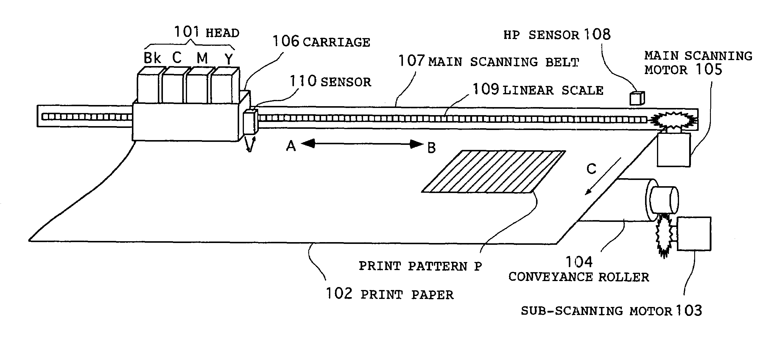
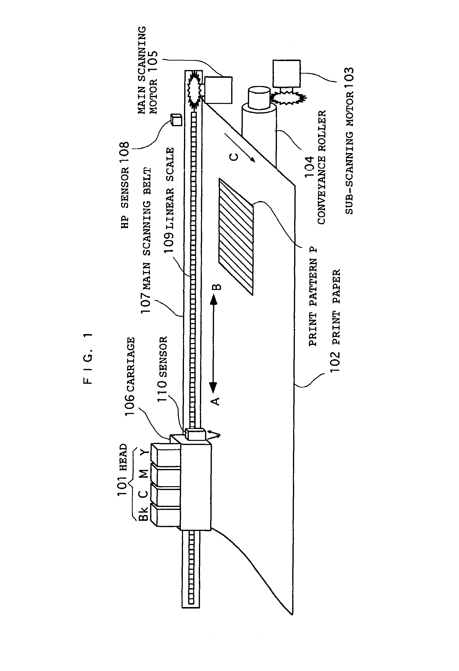
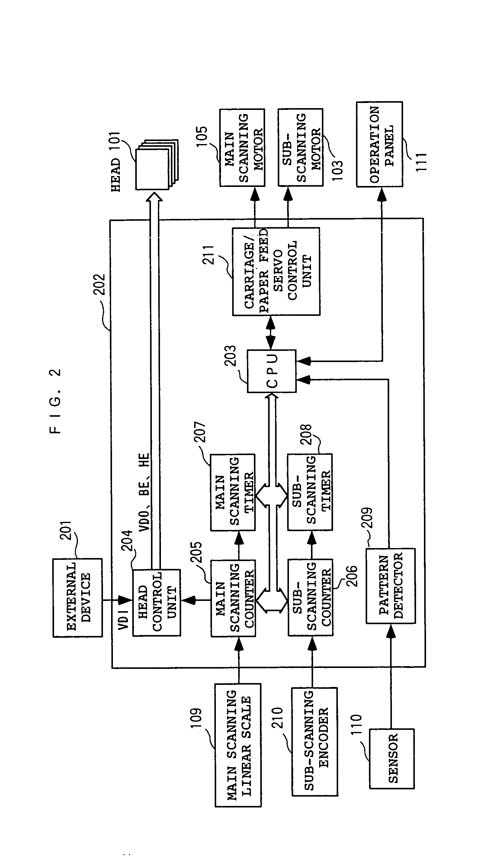
[0057]FIG. 2 is a block diagram showing the configuration of the control hardware of an image forming device in the present invention. The image forming device shown in the figure, which comprises a print control unit 202 and the heads 101, is connected to an external device 201. The external device 201—a computer, an image reader, and some other device—is a host unit which provide the image forming device with image data or commands required for recording.

[0058]Connected to the print control unit 202 are the main scanning linear scale 109, a sub-scanning encoder 210, the main scanning motor 105, sub-scanning motor 103, sensor 110, and an operation panel 111.

[0059]The print control unit 202 receives image data VDI from the external device 201 and controls the formation of an image on the print paper with the use of the heads 101. The print control unit 202 comprises a CPU 203, a head control unit 204, a main scanning counter 205, a sub-scanning counter 206, a main scanning timer 207...

second embodiment

[0086]Next, the present invention will be described. FIG. 17 shows the configuration of an image forming device in this embodiment. The configuration in this figure is almost similar to that shown in FIG. 2 except that a second interrupt generator 212 is added. As shown in the timing chart in FIG. 18, the second interrupt generator 212 sends the second interrupt signal to the CPU 203 when the timing signal is issued from the main scanning linear scale 109 immediately after the pattern detector 209 sends the interrupt signal (first interrupt) to the CPU 203. This second interrupt allows the CPU 203 to know the timer value T1 of the main scanning timer 207 at that moment. In this embodiment, the timer value in the main scanning timer 207 is reset immediately after the timer value T1 is identified. The measured timer value T1 may be different from the theoretical value T0, calculated from the predetermined speed, depending upon the variation in the carriage speed. The figure shows a ca...

third embodiment

Next, the present invention will be described. The configuration of an image forming device in this embodiment is similar to that shown in FIGS. 1 and 2 except the internal configuration and operation of the head control unit 204.

[0088]FIG. 19 shows an example of the internal configuration of the head control unit 204. The head control unit 204 generally comprises an image memory 301, an image memory control unit 302, a mask memory 303, a mask control unit 304, and a heater drive signal generator 305.

[0089]The image memory control unit 302 performs memory control as follows. That is, it temporarily stores into the image memory 301 several bands of serial image data VDI transferred from the external device 201 as described above and, as the head 101 scans, it outputs the stored image data to the head 101 as the image data VDO. When storing the image data VDI into the image memory 301, the unit generates the memory address signal in synchronization with the timing in which data is tra...


PUM


Abstract

A head (101) prints a predetermined test pattern under the control of a head control unit (204) in order to precisely detect a head deviation when a head has been changed, the printed test pattern is read by a sensor 110 and detected by a pattern detector (209). Every time an interrupt signal corresponding to the edge of a detected pattern element is input to the CPU (203), a value of a main scanning counter (205) / main scanning timer (207) (and / or a sub-scanning counter (206) / sub-scanning timer (208)) is read, the printing position of each pattern element is detected from the value, and the mounting deviation of the head is calculated based on the detection result of the printing position of each pattern element printed by the head. The vertical bar of a test pattern may be printed in multiple passes. A plurality of edges may be detected at different longitudinal positions of the bar and the detected results are averaged to determine an edge position.

Description

TECHNICAL FIELD[0001]The present invention relates to an image forming device that forms an image with the ink jet recording method.BACKGROUND ART[0002]In the ink jet recording method, pulse signals are applied to a heater disposed in an ink-filled nozzle to heat the heater, to boil ink, and to cause the boiled ink to increase the vapor pressure to jet ink. To use this method on an image forming device, a plurality of nozzles are arranged to form one recording head, and a plurality of recording heads (for example, for jetting ink in cyan, magenta, yellow, black, and so on) are combined, to form a full-color image.[0003]Conventionally, when forming an image using a plurality of recording heads by the ink jet recording method, the problem is that a horizontal deviation between any two recording heads, as shown in FIG. 14(a), is sometimes introduced when the recording heads are mounted on a carriage at a factory at shipment time or when a service engineer or a user replaces one or more...

Claims


Application Information

Patent Timeline
Patent Type & Authority Patents(United States)
IPC IPC(8): B41J29/393B41J23/00B41J2/21
CPCB41J29/393B41J2/2135
Inventor MATSUDA, YUJI
Owner COPYER
Why Eureka
Try Eureka