Biosensor apparatus and method with sample type and volume detection

a biosensor and sample technology, applied in the field of biosensors, can solve the problems of reducing introducing errors, and improvising diagnosis and treatment, and achieve the effect of accurately detecting the volume of the sampl

Inactive Publication Date: 2005-02-15
LIFESCAN IP HLDG LLC
View PDF13 Cites 181 Cited by
  • Summary
  • Abstract
  • Description
  • Claims
  • Application Information

AI Technical Summary

Benefits of technology

The present invention provides for apparatus and methods that can determine whether a sufficient sample volume was deposited into a biosensor, can accommodate variations in the volume of samples, and can determine the type of sample deposited within the biosensor. The aforementioned problems are overcome by accurately detecting the volume of the sample within the biosensor cell by determining the biosensor cell's effective capacitance, which is proportional to the volume of the sample within the biosensor cell.

Problems solved by technology

If the sample is too small / large, however, the electrical signal will indicate a concentration which is lower / higher than the actual concentration of the component in the sample, resulting in the potential for improper diagnosis and treatment.
Second, an error is introduced if the sample touches a detection conductor without filling the area of the conductor completely.
Third, this method is not able to compensate for bubbles trapped within the sample, which reduces the volume of the sample.
This method relies on a subjective determination of the volume of a sample and is, therefore, prone to errors.
This is especially problematic when the biosensor is used to measure chemical components associated with certain diseases, such as diabetes, that cause decreased visual acuity in the user.
This “go / no-go” method of using biological samples, which relies on the sample volume being within a narrow range, results in wasted time and samples for samples outside this narrow range.

Method used


Image

  • Biosensor apparatus and method with sample type and volume detection
  • Biosensor apparatus and method with sample type and volume detection
  • Biosensor apparatus and method with sample type and volume detection

Examples


Embodiment Construction

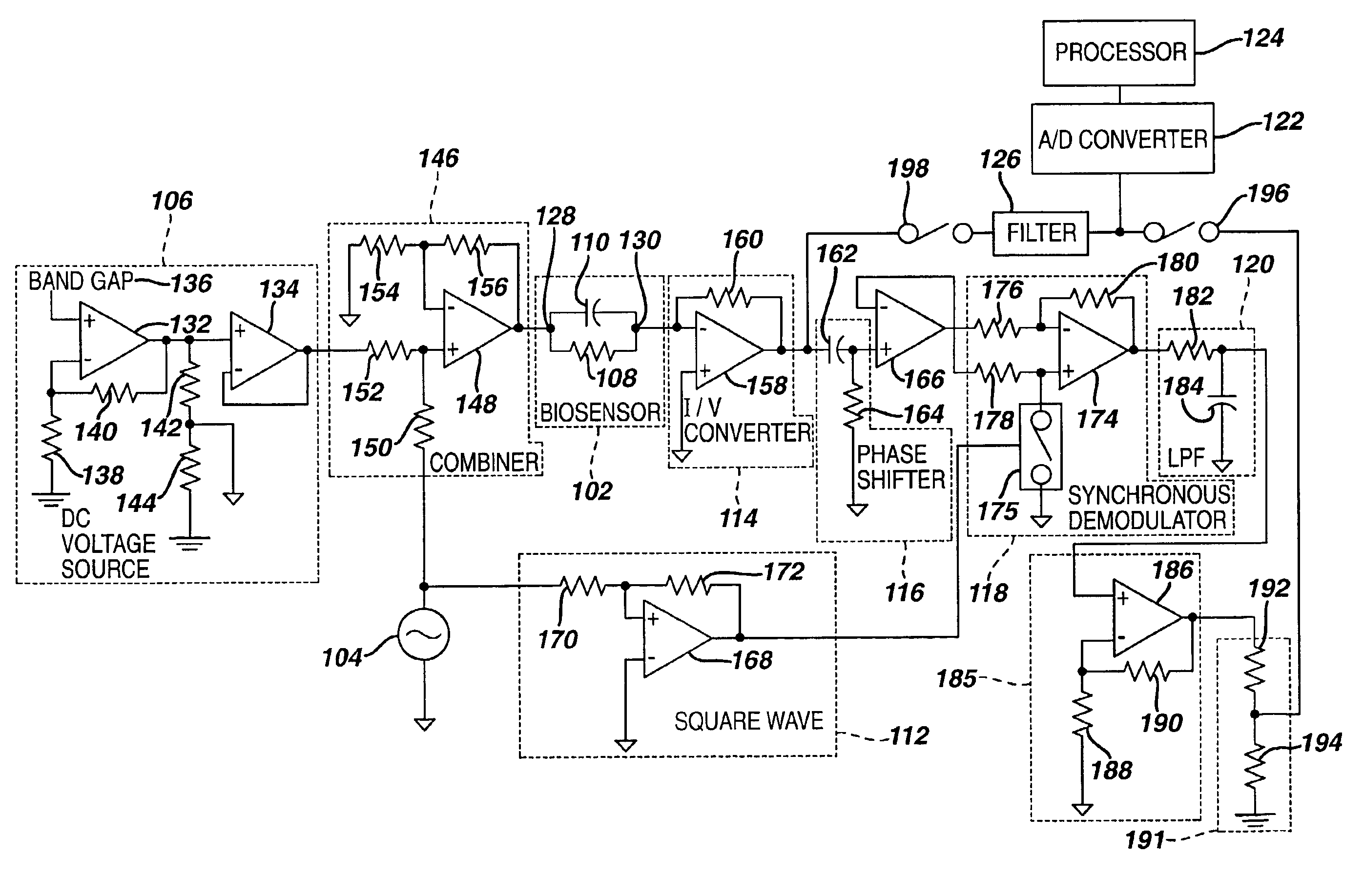
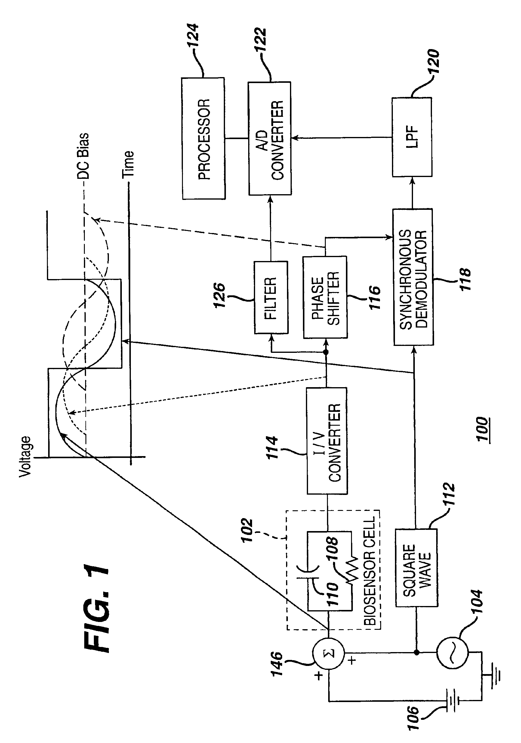
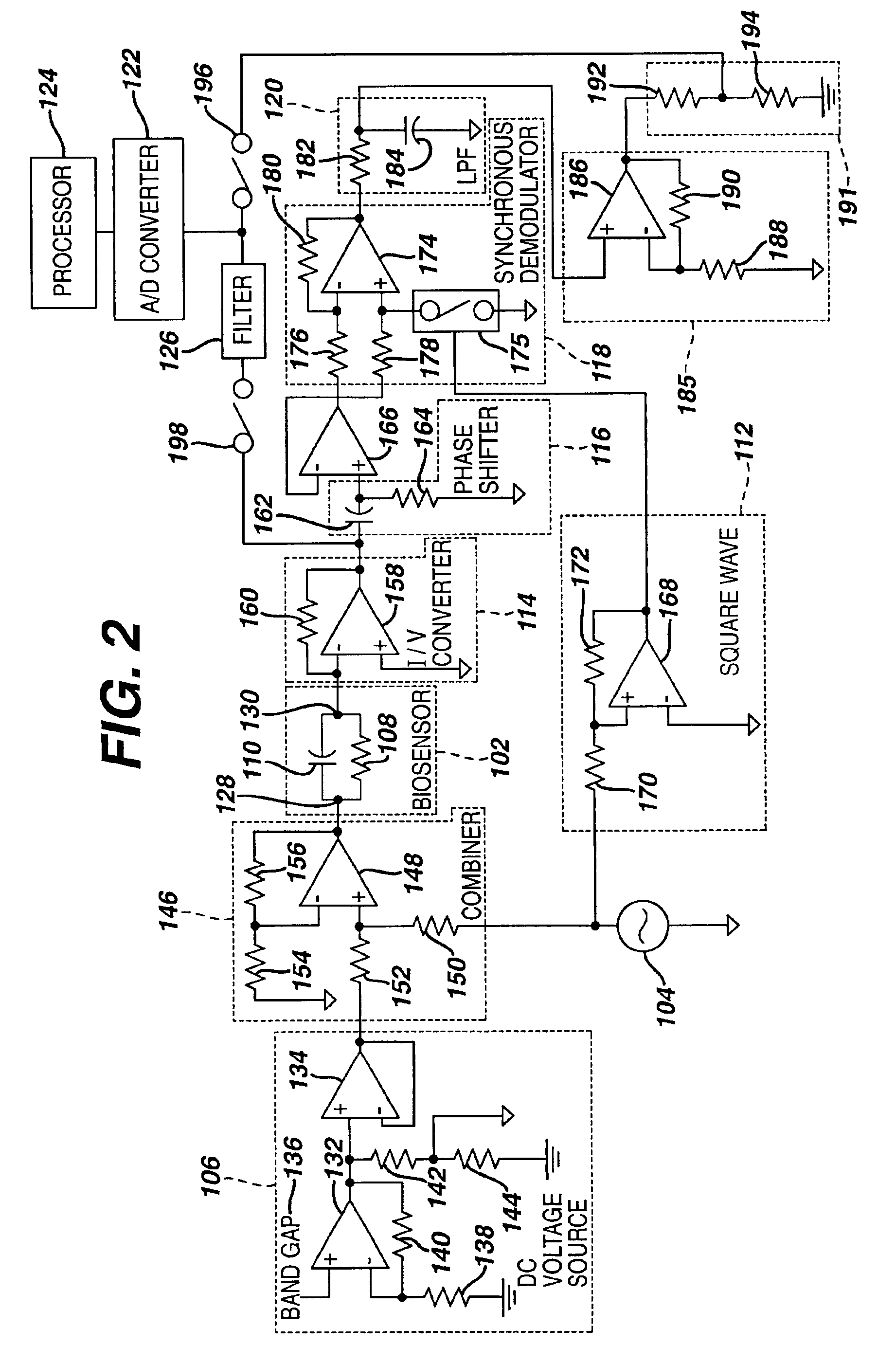
FIG. 1 is a block diagram of biosensor device 100 in accordance with one embodiment of the present invention for determining the volume of a sample positioned within a biosensor cell 102 and the type of sample positioned within the biosensor cell 102. In addition, FIG. 1 depicts signal levels developed at various locations within the biosensor device 100. In a general overview, an AC sine wave generated by an AC sine wave generator 104 and a DC biasing voltage generated by a DC voltage source 106 are combined by a combiner 146 and applied to the biosensor cell 102 to create a signal that reflects the effective resistance 108 and capacitance 110 across the biosensor cell 102. In addition, the AC sine wave is passed to a square wave generator 112 that generates a square wave synchronous with the sine wave. The signal out of the biosensor cell 102 is passed through a current-to-voltage (I / V) converter 114 to convert the signal to a voltage signal. The voltage signal out of the I / V conv...


PUM

PropertyMeasurementUnit
frequencyaaaaaaaaaa
DC voltageaaaaaaaaaa
voltageaaaaaaaaaa

Abstract

A biosensor apparatus and method with sample type and cell volume detection. The apparatus includes a sine wave generator to apply an AC signal to a biosensor cell containing a sample, a current-to-voltage converter, a phase shifter, a square wave generator, a synchronous demodulator, and a low pass filter which yields a signal proportional to the effective capacitance across the biosensor cell, which is proportional to the volume of the sample. In addition, the current-to-voltage converter yields a signal indicative of the type of sample contained within the biosensor cell. The method includes applying a sine wave to the biosensor cell, shifting the phase of the resultant signal, generating a square wave synchronous with the sine wave, demodulating the resultant signal with the square wave, and filtering the demodulated signal to produce a signal proportional to the effective capacitance across the biosensor cell. The biosensor apparatus and method are capable of determining sample type and measuring glucose levels over a wide range of sample volumes.

Description

FIELD OF THE INVENTIONThe present invention relates to biosensors and, more particularly, to a method and apparatus for detecting the type and volume of samples deposited within a biosensor cell.BACKGROUND OF THE INVENTIONA biosensor is a device that measures the presence of various chemical components in a sample deposited in a biosensor cell. For example, a biosensor may be used to measure the amount of glucose present in a sample of blood. Generally, the biosensor cell includes a pair of conductors, e.g., gold and palladium, configured to receive a sample therebetween. Typically, the biosensor generates an electrical signal that is proportional to the amount of a certain component, e.g., glucose, in a sample, which is assumed to have a certain volume. If the sample is too small / large, however, the electrical signal will indicate a concentration which is lower / higher than the actual concentration of the component in the sample, resulting in the potential for improper diagnosis and...

Claims


Application Information

Patent Timeline
Patent Type & Authority Patents(United States)
IPC IPC(8): G01N27/22G01N33/487A61B5/145G01F23/26A61B5/1473G01N27/416G01N33/483G01N33/50G01N33/66G01R27/26
CPCG01N27/3273G01R27/2605G01N33/54373G01N33/50
Inventor KERMANI, MAHYAR ZARDOSHTI
Owner LIFESCAN IP HLDG LLC
Why Eureka
Try Eureka