Vehicle classification and axle counting sensor system and method

a technology of vehicle classification and axle counting, applied in the field of object sensors, can solve the problems of high system cost of using several sensors, added complexity of integrating different sensors into a single system, etc., and achieve the effect of accurately detecting vehicle axles and accurately determining the shape and speed of vehicles

Inactive Publication Date: 2002-10-03
WANGLER RICHARD J +3
View PDF0 Cites 186 Cited by
  • Summary
  • Abstract
  • Description
  • Claims
  • Application Information

AI Technical Summary

Benefits of technology

[0011] In view of the foregoing, it is an object of the invention to accurately determine the shape and speed of a vehicle. It is further an object to provide a three-dimensional profile of the moving vehicle for use in classifying the vehicle. It is yet another object to accurately detect vehicle axles for further classification of the vehicle.
[0016] Scanning is provided using an optically reflective mirror surface intercepting the beams and reflecting the beams at predetermined angles from a perpendicular to the roadway. The beams reflected off the vehicle are directed back toward the mirror into corresponding apertures of the receivers. Means are provided for rotatably moving the reflective surface across a reflective angle sufficient for reflecting the beams across a transverse portion of the vehicle, and signal means representative of the sensor angle within the beam plane are also provided. The angle signals are processed for providing range data at corresponding angles. The range and angle data in combination provide a transverse profile of the vehicle.

Problems solved by technology

Along with the disadvantages of embedding a sensor in the road, the higher system cost of using several sensors, and added complexity of integrating different sensors into a single system, transportation professionals at all levels have expressed an increased interest in an overhead sensor that is capable of counting axles.

Method used


Image

  • Vehicle classification and axle counting sensor system and method
  • Vehicle classification and axle counting sensor system and method
  • Vehicle classification and axle counting sensor system and method

Examples


Embodiment Construction

[0049] The present invention will now be described more fully hereinafter with reference to the accompanying drawings, in which preferred embodiments of the invention are shown. This invention may, however, be embodied in many different forms and should not be construed as limited by the embodiments set forth herein. Rather, these embodiments are provided so that this disclosure will be thorough and complete, and will fully convey the scope of the invention to those skilled in the art. Like numbers refer to like elements throughout.

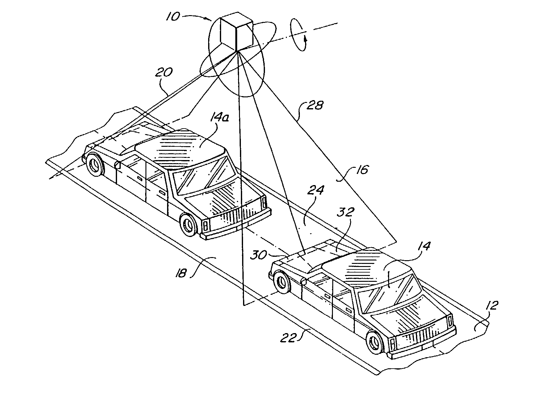
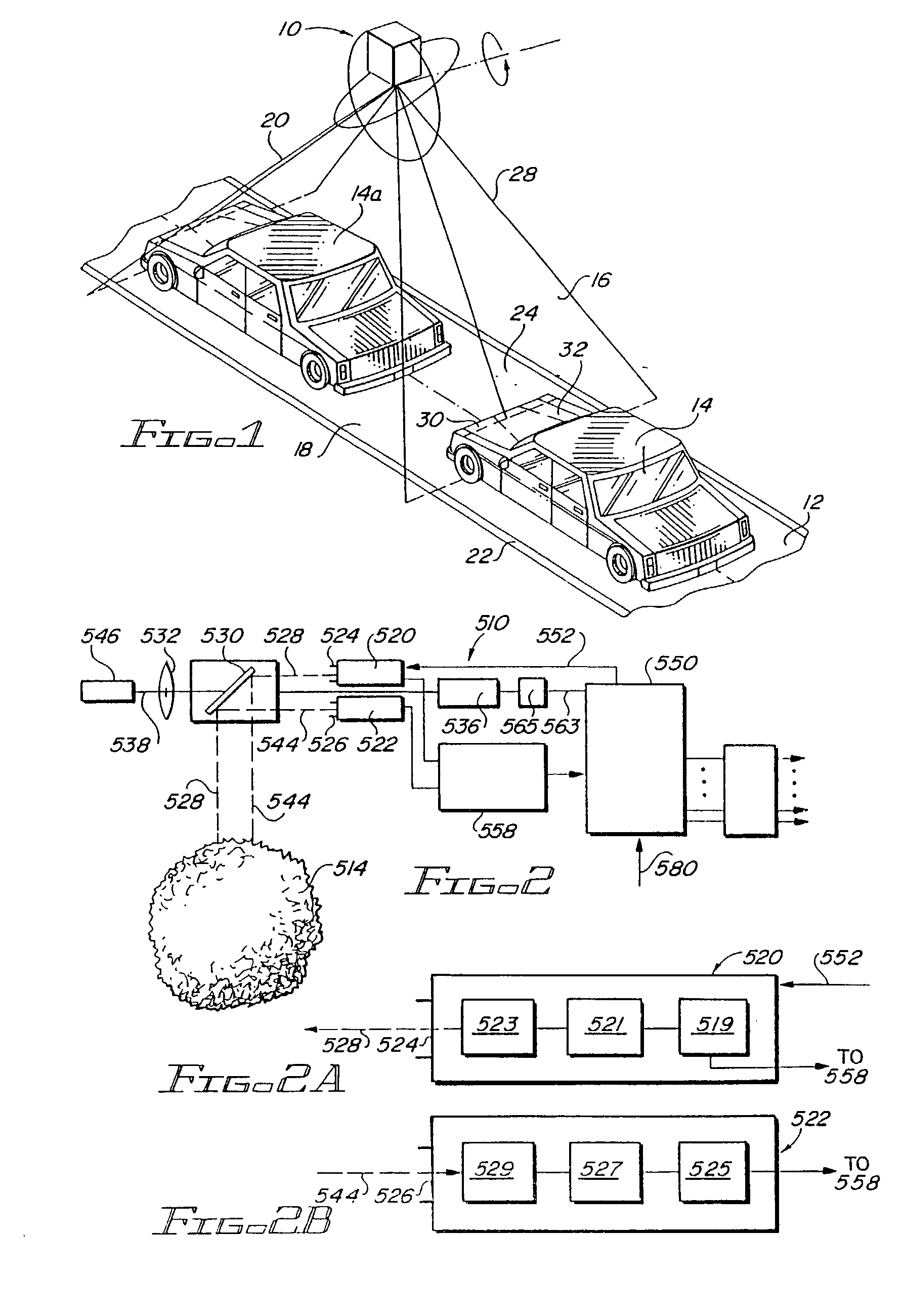
[0050] With reference initially to FIG. 1, a sensor 10 is affixed above a highway 12 for sensing a vehicle 14 passing below the sensor 10. A forward scanned beam 16 intercepts the vehicle 14 as the vehicle passes through an area 18 below the sensor 10 and a backward scanned beam 20 intercepts the vehicle 14a as the vehicle leaves the sensor area 18.

[0051] Reference numerals for elements described in related U.S. Pat. No. 5,321,490 for the Active Near-Fiel...


PUM


Abstract

A vehicle detection and classification sensor provides accurate 3D profiling and classification of highway vehicles for speeds up to 100 mph. A scanning time-of-flight laser rangefinder is used to measure the distance to the highway from a fixed point above the road surface and then measure the distance to the surfaces of any vehicle that is viewed by the sensor. The beam is pulsed at a high repetition rate for determining vehicle speeds with a high accuracy and uses the calculated speed and consecutive range measurements as the vehicle moves past the sensor to develop a three-dimensional profile of the vehicle. An algorithm is applied to the three-dimensional profile for providing a vehicle-classification. A laser is also used to count the number of axles associated with the vehicle.

Description

[0001] 1. Field of the Invention[0002] The present invention relates generally to object sensors and related methods, and in particular to electronic object sensors and methods useful in detecting vehicle speed and shape for classification and input to Intelligent Vehicle Highway Systems (IVHS).[0003] 2. Background Art[0004] A vehicle sensor detecting the presence of a vehicle in a traffic lane and indicating the vehicle speed as it passes the sensor is described in U.S. Pat. No. 5,321,490 referenced above and co-owned with the present invention. A time-of-flight laser rangefinder is used to measure the normal distance to a road surface from a fixed point above the road surface and then measures the distance to a vehicle that either passes or stops under the sensor. Two laser beams pulsing at a high rate are projected across the road surface at a fixed angle between them. Because of the high repetition rate of the pulsed beam, the system is able to determine vehicle speed with an ac...

Claims


Application Information

Patent Timeline
Patent Type & Authority Applications(United States)
IPC IPC(8): G01S17/89G01S7/48G01S17/88G08G1/015G08G1/04
CPCG01S7/4802G01S7/4817G08G1/04G01S17/89G08G1/015G01S17/88
Inventor WANGLER, RICHARD J.MYERS, JOHN T.GUSTAVSON, ROBERT L.MCCONNELL, ROBERT E. II
Owner WANGLER RICHARD J
Why Eureka
Try Eureka