Shift lever device

a technology of lever device and lever, which is applied in the direction of gearing control, gearing element, belt/chain/gearing, etc., can solve the problems of affecting the amount of backlash fluctuating, and the cam and the detent rod may be affected by backlash, so as to improve the operation of the button. the effect of button operation and improving the operation feeling

Active Publication Date: 2019-12-31
TOYOTA JIDOSHA KK
View PDF28 Cites 0 Cited by
  • Summary
  • Abstract
  • Description
  • Claims
  • Application Information

AI Technical Summary

Benefits of technology

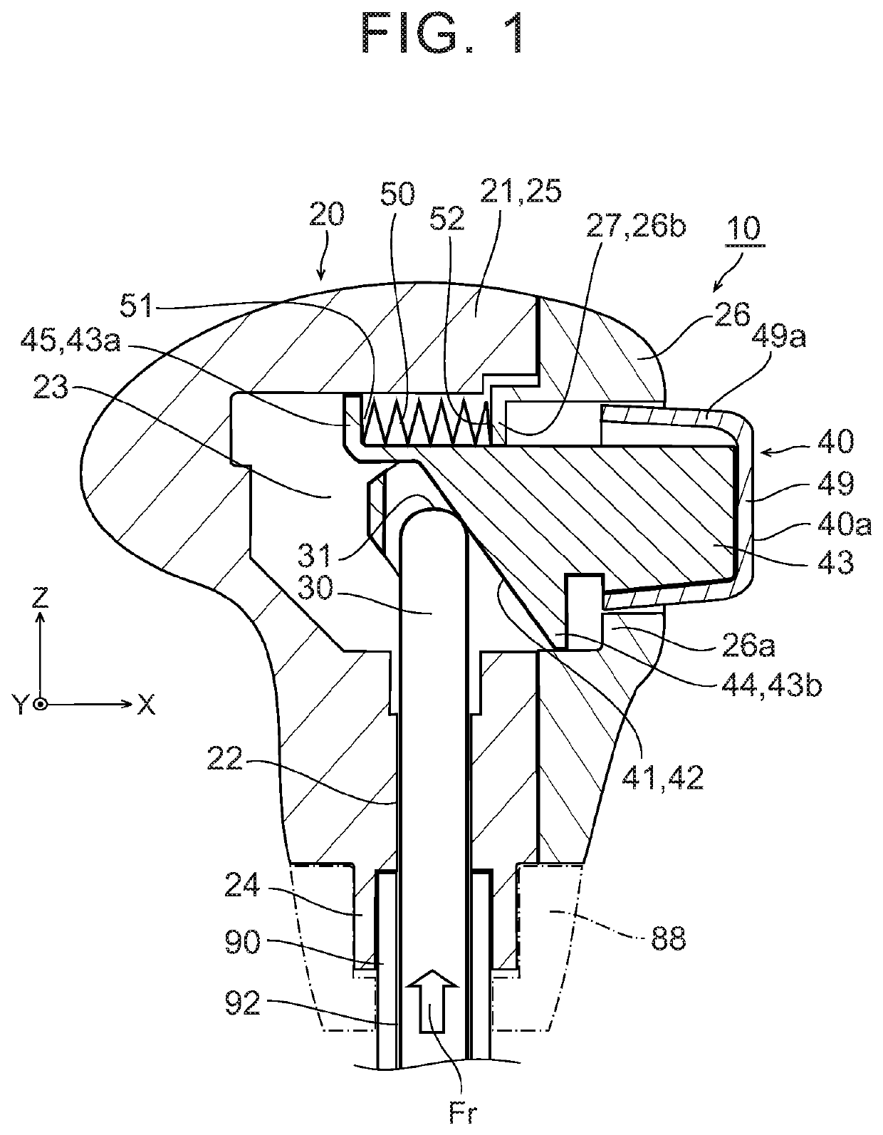
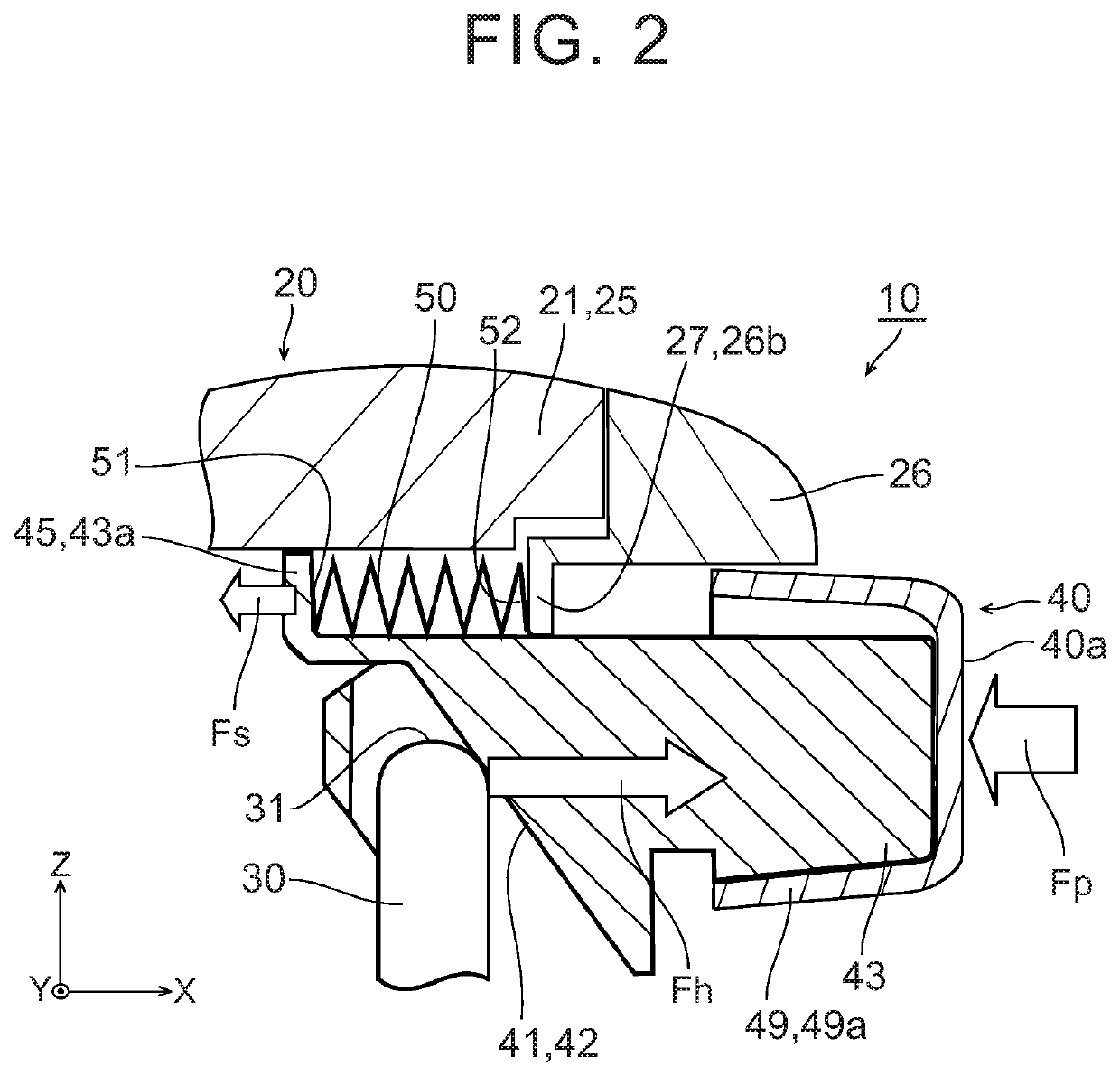
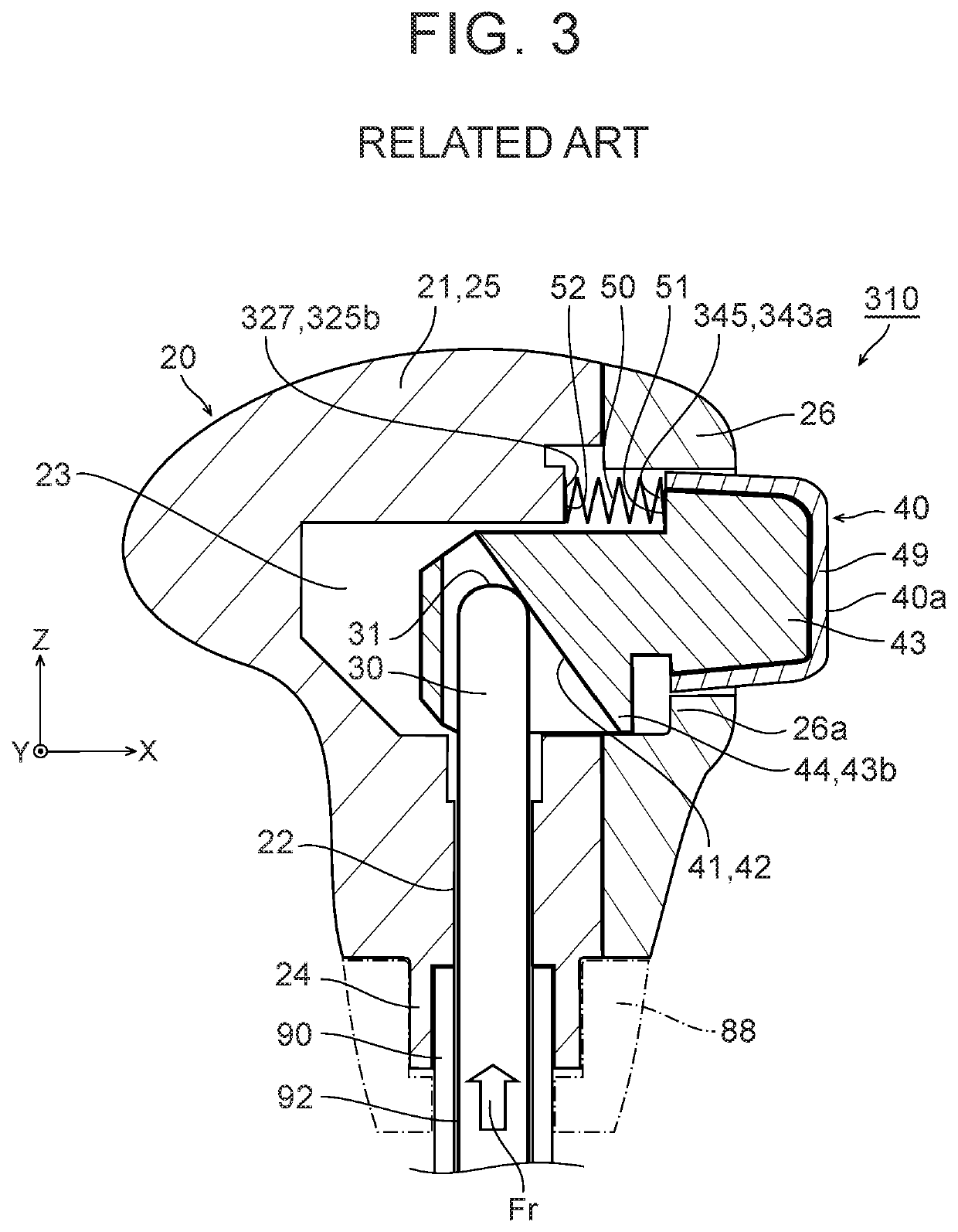
[0008]However, in the shift lever device described in Japanese Patent Application Publication No. 2000-043600 (JP 2000-043600 A), the cam is always urged in such a direction as to recede from the detent rod. Therefore, a backlash is formed between the cam and the detent rod. Due to the presence of this backlash, a feeling of strangeness may be developed as a result of rapid changes in the operational load of the button at the time of operation. Besides, the waiting position of the detent rod differs depending on whether the parking position or the reverse position is selected. Thus, the amount of backlash fluctuates, and the operation of pressing the unlocking button inward is inconstant. Besides, the unlocking button is urged in the direction opposite to the direction of operation. Thus, the operational load may increase, and an extra force may be required in operating the button of the shift lever. As described hitherto, the aforementioned shift lever device has room of improvement in operational feeling in operating the button.
[0009]The disclosure provides a vehicular shift lever device that has a button portion for canceling limitations on changes in shift position and that can improve an operational feeling of button operation in canceling the limitations on the changes in shift position.

Problems solved by technology

Therefore, a backlash is formed between the cam and the detent rod.
Due to the presence of this backlash, a feeling of strangeness may be developed as a result of rapid changes in the operational load of the button at the time of operation.
Thus, the amount of backlash fluctuates, and the operation of pressing the unlocking button inward is inconstant.
Thus, the operational load may increase, and an extra force may be required in operating the button of the shift lever.

Method used


Image

  • Shift lever device
  • Shift lever device
  • Shift lever device

Examples


second embodiment

[0090]Next, a shift lever device 110 according to the second embodiment of the disclosure will be described. FIG. 11 is a longitudinal sectional view schematically showing the shift lever device 110, and FIG. 12 is a right lateral view of the shift lever device 110. The shift lever device 110 is identical to the shift lever device 10 except in that the contour of the shift knob 20 is downsized and that a different mode of supporting the spring member 50 is adopted. Thus, redundant description will be omitted.

[0091]In the shift lever device 110, the movable end 51 of the spring member 50 is supported by the abutment portion 45 of the button portion 40, and the fixed end 52 of the spring member 50 is supported by the spring retaining portion 27 of the shift knob 20. In the shift lever device 110, the abutment portion 45 is provided at a protrusion portion 43c that protrudes upward from a middle of the button body portion 43. The protrusion portion 43c of the shift lever device 110 is ...

third embodiment

[0094]Next, a shift lever device 210 according to the third embodiment of the disclosure will be described. FIG. 13 is a longitudinal sectional view schematically showing the shift lever device 210, and FIG. 14 is an exploded perspective view of the shift lever device 210. The shift lever device 210 is identical to the shift lever device 110 except in that a different mode of supporting the spring member 50 is adopted. Thus, redundant description will be omitted. In particular, the spring member 50 of the shift lever device 210 is disposed between the rod member 30 and the button top 40a in the right-left direction as the second direction.

[0095]In the shift lever device 210, the movable end 51 of the spring member 50 is supported by the abutment portion 45 of the button portion 40, and the fixed end 52 of the spring member 50 is supported by the spring retaining portion 27 of the shift knob 20. The button portion 40 is provided with a spring hole 43f and a spring groove 43g that is ...


PUM


Abstract

A shift lever device includes a shift knob, a rod member including a first portion. The rod member is configured to cancel limitations on changes in a shift position by moving in a first direction. And the shift lever device includes a button portion including a second portion configured to engage the first portion and a button top protruding from the shift knob. The button portion is configured to move the rod member in the first direction by moving in a second direction when the first portion and the second portion are in contact with each other. And the shift lever device includes an urging member. The urging member is configured to urge the button portion such that the second portion approaches the first portion.

Description

INCORPORATION BY REFERENCE[0001]The disclosure of Japanese Patent Application No. 2015-243057 filed on Dec. 14, 2015 including the specification, drawings and abstract is incorporated herein by reference in its entirety.BACKGROUND OF THE DISCLOSURE[0002]1. Field of the Disclosure[0003]The disclosure relates to a shift lever device.[0004]2. Description of Related Art[0005]In Japanese Patent Application Publication No. 2000-043600 (JP 2000-043600 A), there is described a shift lever device that is provided with a limitation mechanism for limiting inadvertent changes to a reverse position for reversely driving driving wheels and a parking position for locking the driving wheels.[0006]By the way, the shift lever device described in Japanese Patent Application Publication No. 2000-043600 (JP 2000-043600 A) is equipped with a shift lever that changes a shift position of an automatic transmission through shift operation, a detent rod that avoids detent means, an unlocking button that displ...

Claims


Application Information

Patent Timeline
Patent Type & Authority Patents(United States)
IPC IPC(8): F16H59/02F16H59/10
CPCF16H59/0278F16H59/10F16H2059/0282
Inventor TAKAKUWA, KEI
Owner TOYOTA JIDOSHA KK
Why Eureka
Try Eureka