Servo error detection and compensation utilizing virtual data tracking servo methods

Active Publication Date: 2008-10-30
QUANTUM CORP
View PDF99 Cites 21 Cited by
  • Summary
  • Abstract
  • Description
  • Claims
  • Application Information

AI Technical Summary

Benefits of technology

[0007]According to one aspect of the present invention methods and systems are provided for determining errors in a servo system (e.g., an optical or magnetic servo system) associated with a tape drive. In one example, a method for detecting errors in a servo system includes writing a plurality of data tracks to a storage medium at a pitch, detecting a position of an edge of at least two of the plurality of data tracks under control of a servo system (e.g., an optical servo system), and determining an error in the servo system based on the detected positions and the pitch of the data tracks. In one example, the plurality of data tracks are written according to a track trimming format (and without use of the drive servo system), wherein a first track is written to the storage medium followed by a second track partially overlapping or “trimming” the first track. Subsequent tracks each trim a previously written track forming a plurality of tracks at a known pitch.

Problems solved by technology

Differences in the track edge positions or pitch of the plurality of data tracks from the pitch at which they were written may indicate errors in the optical servo system (e.g., non-linear errors, as well as other errors such as electrical, temperature, or the like).

Method used


Image

  • Servo error detection and compensation utilizing virtual data tracking servo methods
  • Servo error detection and compensation utilizing virtual data tracking servo methods
  • Servo error detection and compensation utilizing virtual data tracking servo methods

Examples


Embodiment Construction

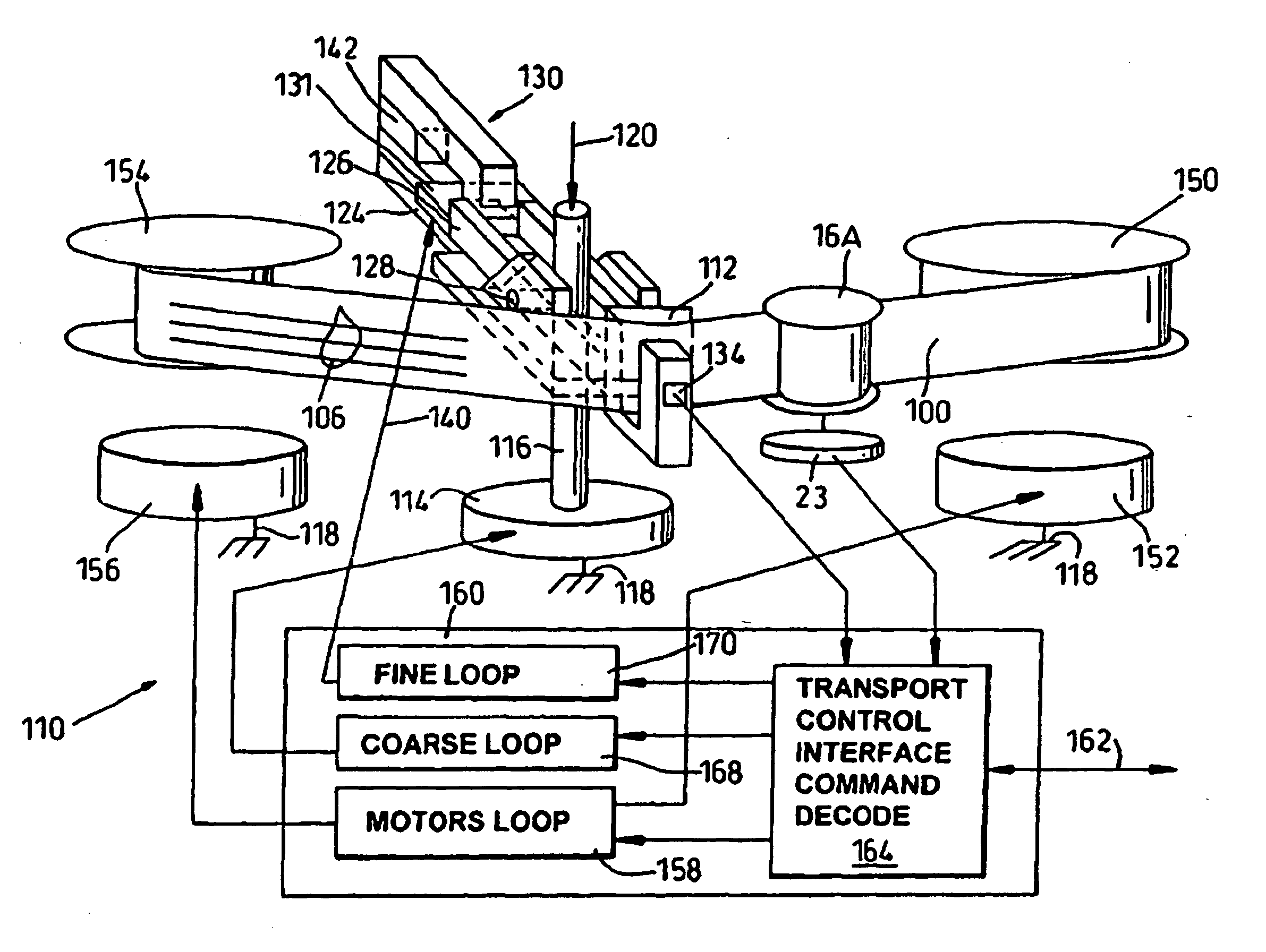
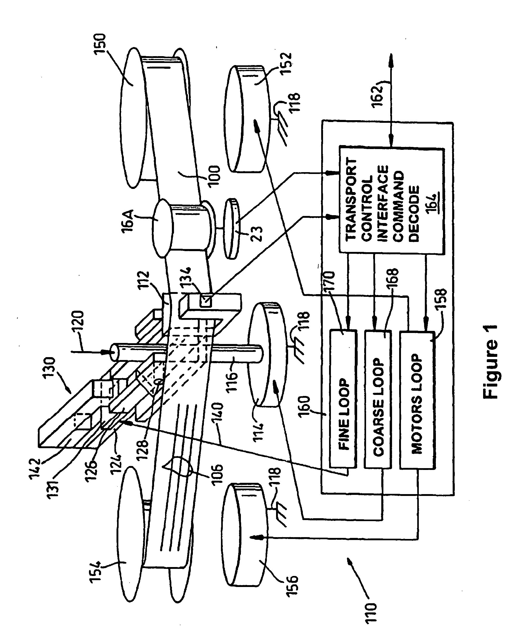
[0020]Various methods and systems for providing calibration and / or position information for a servo system, e.g., a primary servo system or subsystem servo system, are provided. The following description is presented to enable a person of ordinary skill in the art to make and use various aspects of the inventions. Descriptions of specific materials, techniques, and applications are provided only as examples. Various modifications to the examples described herein will be readily apparent to those skilled in the art, and the general principles defined herein may be applied to other examples and applications without departing from the spirit and scope of the inventions.

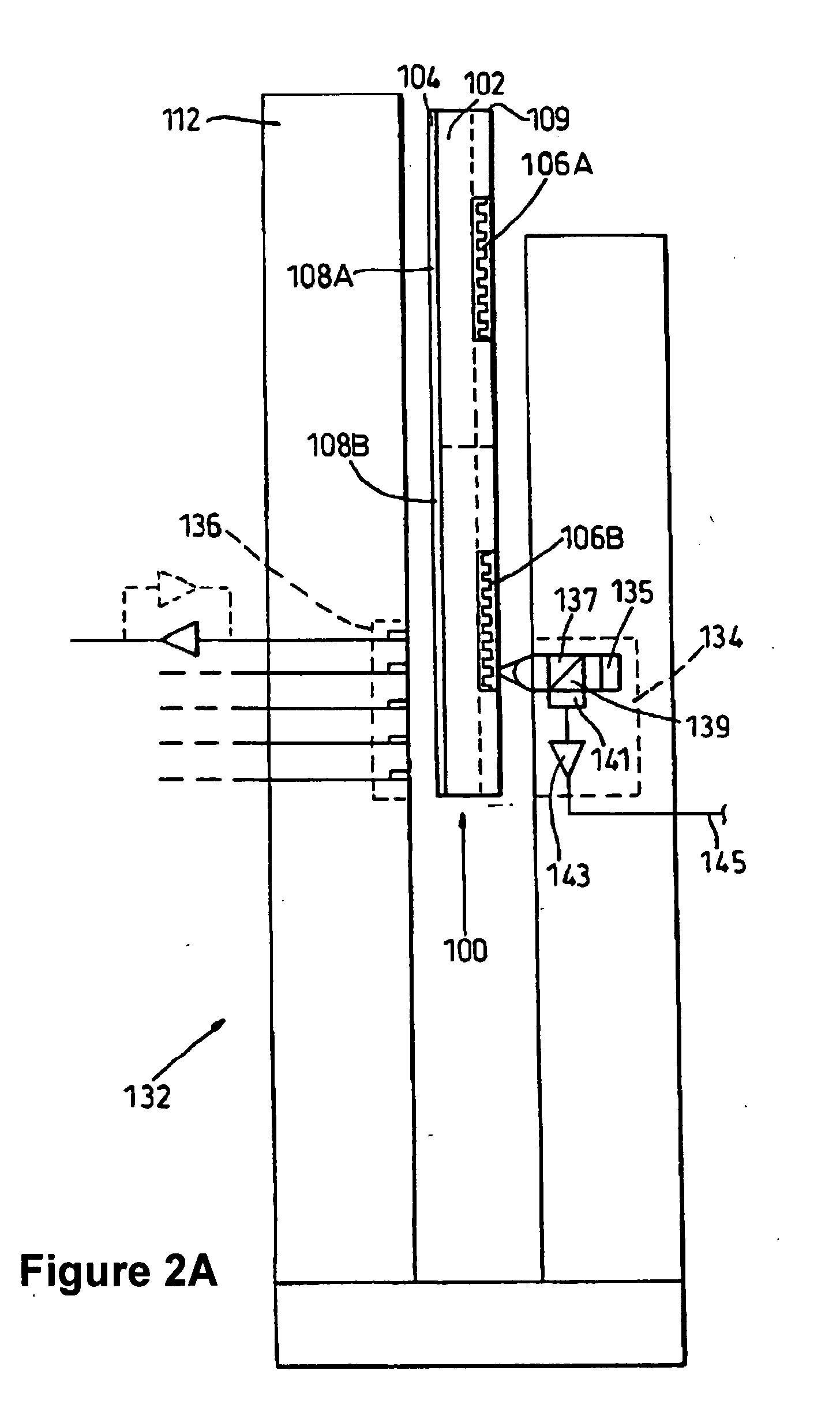
[0021]Typical optical servo system included with magnetic tape drives generally operate by directing light, e.g., a laser beam, to a known pattern of optical indicia associated with the magnetic tape. One drawback of such optical servo systems, however, is that the optical beam / laser “spot” may not be well matched to the...


PUM

PropertyMeasurementUnit
linear relative velocityaaaaaaaaaa
widthaaaaaaaaaa
storage densityaaaaaaaaaa

Abstract

A method for detecting errors in a servo system of a magnetic storage drive includes writing a plurality of data tracks at a pitch, detecting a position of an edge of at least two of the data tracks under control of a servo system (e.g., an optical or magnetic servo system), and determining an error in the servo system based on the detected positions and known pitch of the data tracks. Differences in the track edge positions of the tracks from the positions at which they were written may indicate errors in the optical servo system (e.g., non-linearity errors, as well as other errors such as electrical, temperature, or the like). Determined errors may be stored with a look-up table of positional errors or used to normalize a position algorithm associated with the servo system.

Description

BACKGROUND[0001]1. Field[0002]The invention relates generally to magnetic tape storage devices and systems, and more particularly to methods and systems for detecting and compensating for errors in a head position servo system of a magnetic tape storage drive.[0003]2. Related Art[0004]Increased data storage capacity, and retrieval performance, is desired of all commercially viable mass storage devices and media. In the case of linear tape recording a popular trend is toward multi-head, multi-channel fixed head structures with narrowed recording gaps and data track widths so that many linear data tracks may be achieved on a tape medium of a predetermined width, such as one-half inch width tape. To increase the storage density for a given cartridge size the bits on the tape may be written to smaller areas and on a plurality of parallel longitudinal tracks. As more data tracks are recorded on a tape, each track becomes increasingly narrow. The tape therefore becomes more susceptible to...

Claims


Application Information

Patent Timeline
Patent Type & Authority Applications(United States)
IPC IPC(8): G11B27/36G11B5/00G11B5/127
CPCG11B5/455G11B5/584G11B20/18G11B2020/1281G11B2220/93
Inventor SALIBA, GEORGE A.WHITE, THERON S.DJALALI, AMIRCHEN, HONG
Owner QUANTUM CORP
Why Eureka
Try Eureka