Electrically Traceable and Identifiable Fiber Optic Cables and Connectors

a technology of fiber optic cables and connectors, which is applied in the field of optical fiber cables and systems, can solve the problems of ineffective electronic tone tracing techniques for locating fiber optic cables, difficult non-invasive access, and inability to locate conductors embedded in cable jackets, etc., and achieves the effect of convenient contact and quick locating and identifying

Inactive Publication Date: 2008-11-06
TELESCENT
View PDF11 Cites 163 Cited by
  • Summary
  • Abstract
  • Description
  • Claims
  • Application Information

AI Technical Summary

Benefits of technology

[0011]It is the object of this invention to provide fiber optic cables that include unique design features for readily locating and identifying fiber optic cable and its termination locations. We disclose fiber optic cables with external, continuous and conductive traces provided within physically recessed channels formed in the outer surface of the cable jacket. The one or more r

Problems solved by technology

Nevertheless, the deployment of fiber optic cable does introduce challenges which make the installation, maintenance and operation of a fiber-based network demanding compared to the traditional copper-based network.
In particular, one attribute of copper-based cables which is deficient in fiber optic cables is the ability to wirelessly trace the physical locations and termination points of cables throughout a network; for example, along a cable tray or within wall and ceiling plenums.
Electronic tone-tracing techniques are ineffective in locating fiber optic cables, as typical fiber optic cables do not incorporate the electrical conductors that are needed to transmit an RF tone.
Certain types of composite fiber optic cables include conductors that are embedded within the cable jacket and are difficult to access in a non-invasive fashion.
As a consequence, present day optical detection techniques are unable to trace the fiber in a wireless fashion and can not be performed if the cable lies behind obstructions such as a wall, ceili

Method used


Image

  • Electrically Traceable and Identifiable Fiber Optic Cables and Connectors
  • Electrically Traceable and Identifiable Fiber Optic Cables and Connectors
  • Electrically Traceable and Identifiable Fiber Optic Cables and Connectors

Examples


Embodiment Construction

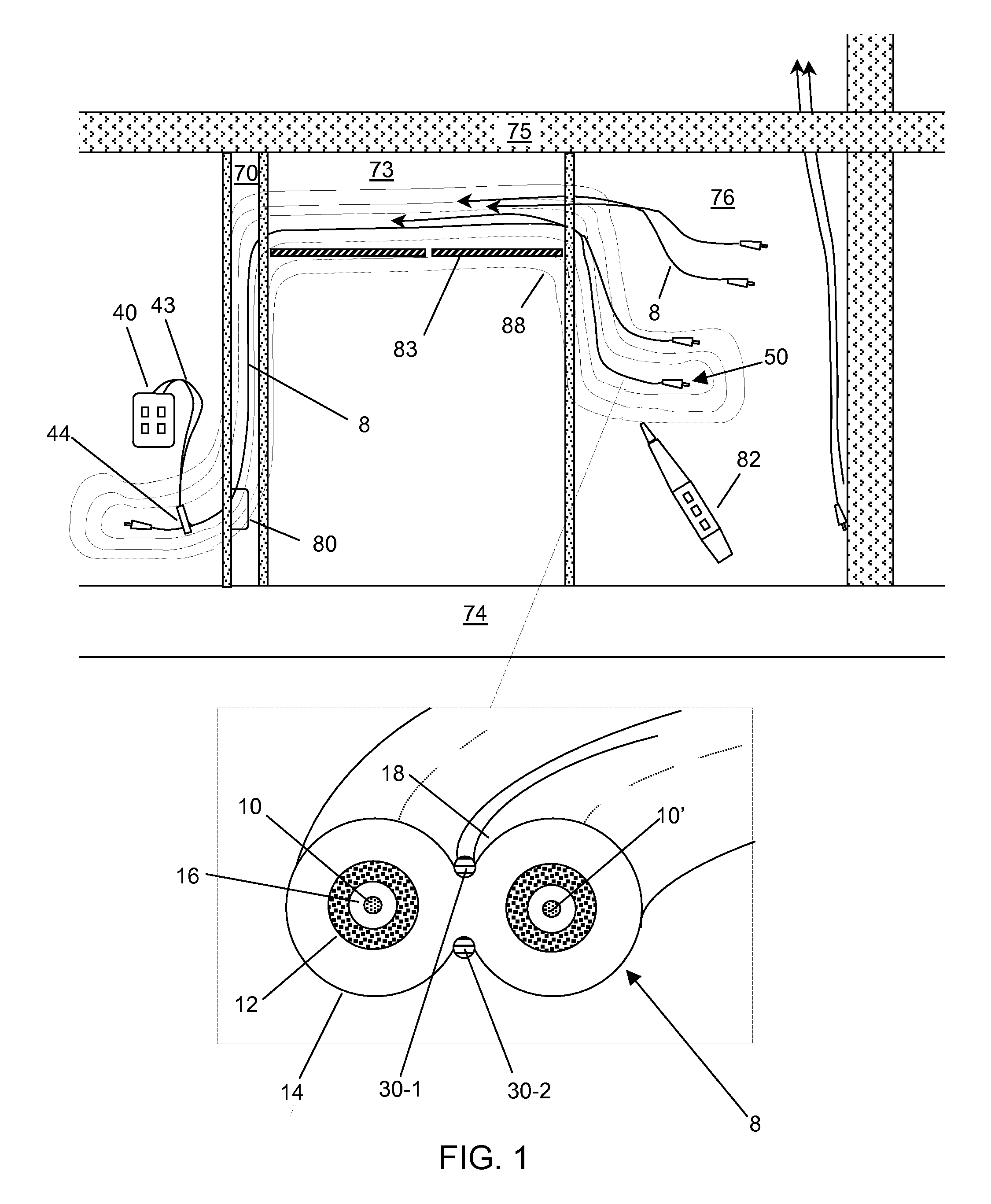
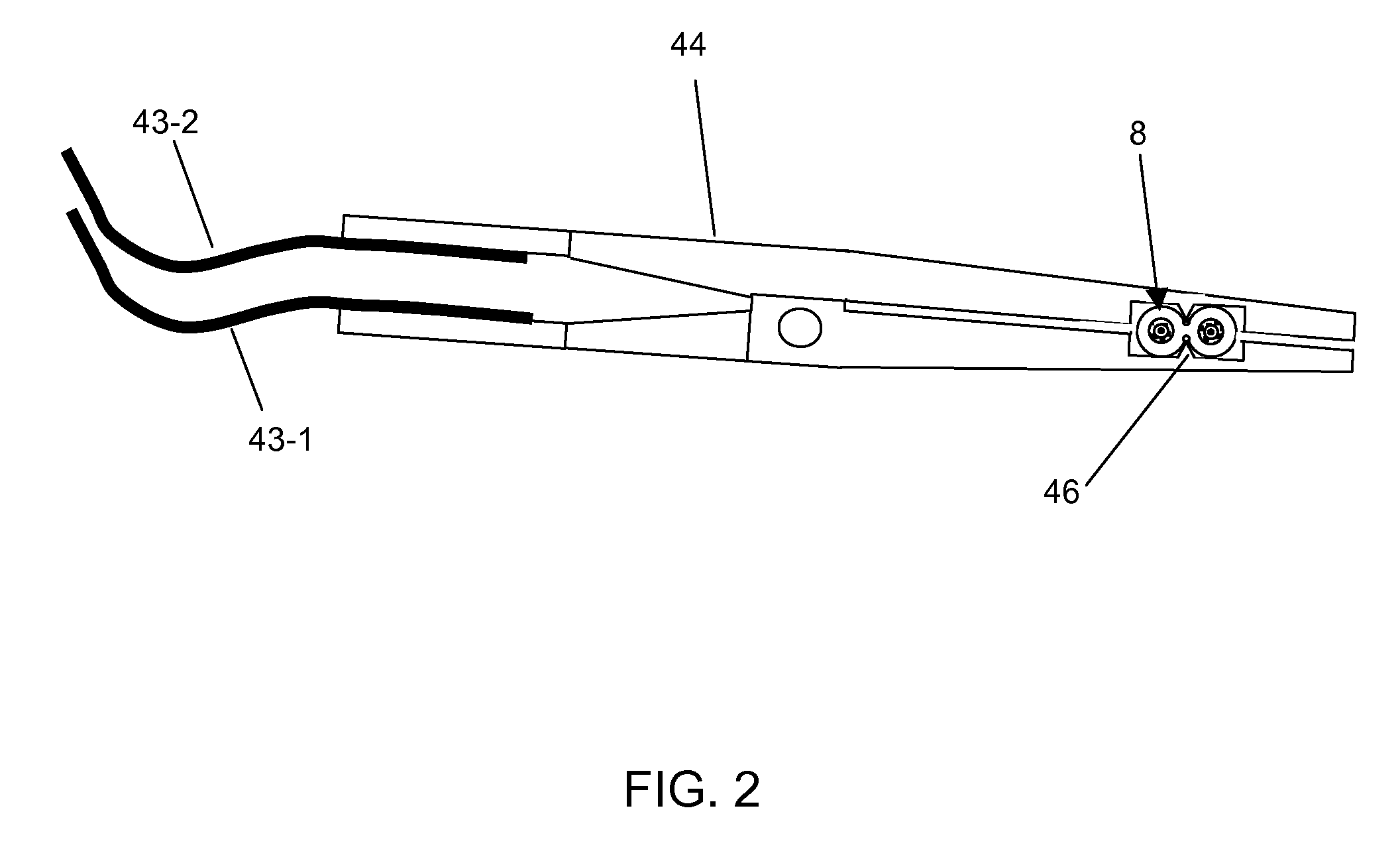
[0020]In this invention, we disclose electrically traceable and identifiable fiber optic cables including one or more externally accessible conductive elements disposed within one or more concavities in the outer surface of the cable jacket, the concavities being longitudinally coextensive with the cable length and parallel or spirally arranged relative to the internal optical fiber. Electrical isolation of these uninsulated conductors, when in contact with other conductive elements, is maintained by fixedly attaching each conductor to a channel region bounded above by a tangential surface joining high points on the cable jacket surface and below by the depression in the cable jacket surface. The electrical isolation resulting from this structure prevents stray electrical conduction between adjacent conductive surfaces or bodies, such as other cables or grounded conduits, while enabling non-invasive electrical contact to the conductor(s) at any point along the length of the cable. T...


PUM


Abstract

Composite fiber optic cables having exposed, conductive traces external to the cable jacket enable non-invasive, wireless electrical tone tracing of fiber optic cables. The cross sectional geometry of the fiber optic cable prevents conductive traces from short circuiting when abutting other cables or grounded conductive elements. Moreover, the structure allows convenient electrical contact to the conductive traces at any location along the longitudinal extent of the cable without requiring penetration of the cable jacket or removal of fiber optic connectors. Traceable fiber optic cables of various types are disclosed, including simplex, duplex and ribbon cables. Systems of traceable cables utilizing connectors with integrated electrical antenna elements attached to the conductive elements of cable and RFID tags for remote connector port identification are further disclosed.

Description

REFERENCE TO RELATED APPLICATIONS[0001]This application is based on provisional patent application 60 / 927,773 filed on May 4, 2007 and entitled “Electrically Traceable Fiber Optic Cables”.FIELD OF THE INVENTION[0002]This invention pertains to optical fiber cables and systems to transmit illumination and / or signals, and more particularly, to fiber optic cables which are electrically traceable and identifiable such that the inventory of physical fiber connections comprising a communications network can be determined by electronic and software means and to systems for electronic tracing of such cables.BACKGROUND OF THE INVENTION[0003]Fiber optic links can provide greater than THz bandwidths over long distances by transmitting one or more data streams at speeds in excess of 10's of Gigabits per second on a single fiber. Optical fiber offers several desirable characteristics, including low transmission loss, very compact size, light weight and relatively low cost. Nevertheless, the deplo...

Claims


Application Information

Patent Timeline
IPC IPC(8): G02B6/44
CPCG02B6/3895G02B6/447G02B6/562
Inventor KEWITSCH, ANTHONY S.
Owner TELESCENT
Why Eureka
Try Eureka