

Oil-well cement fluid loss additive compostion
a technology of cement fluid and additives, which is applied in the direction of chemistry apparatus and processes, well accessories, sealing/packing, etc., can solve the problems of bridging of annulus, premature gelation of cement slurry, and reducing pumping tim
- Summary
- Abstract
- Description
- Claims
- Application Information
AI Technical Summary
Problems solved by technology
Method used
Image

Examples
examples 1-12
Aqueous Fluidized Polymer Suspensions
[0028]Examples 1-12 are examples of various aqueous fluidized polymer suspensions are set forth in the following tables. All amounts are by weight, unless otherwise indicated.
[0029]The viscosity of the aqueous fluidized polymer suspensions of the present invention were determined using a Brookfield viscometer with a number 3 spindle and at 30 revolutions per minute. The viscosities are listed in centipoise cPs.
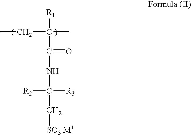
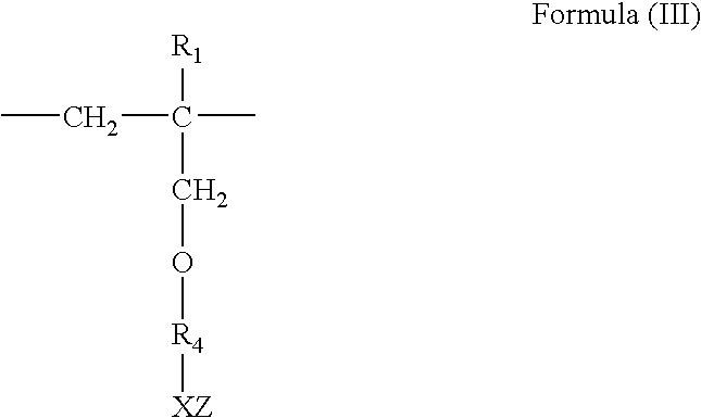
[0030]The aqueous fluidized polymer suspensions were made according to the teachings set forth in U.S. Pat. Nos. 4,883,536 and 5,228,908 where the salt is first added to the water and dissolved to produce an aqueous solution. Subsequently, the allyloxy based co-polymer and the water soluble polymer used in the suspension are added to the aqueous solution and mixed to produce the aqueous fluidized polymer suspensions of the present invention.
EXAMPLE 1SpecificViscosityTotalGravitygramscPspHSolids, %(g / cc).allyloxy based50014206.5141.21.25co-p...
examples 13-21
Cement Formulations
[0032]Examples 13-21 are examples of cement formulations produced using various aqueous fluidized polymer suspensions examples as described above in order to demonstrate the performance of the aqueous fluidized polymer suspensions of the present invention in cementing applications. These cement formulations were tested at various temperatures for Fann Rheology as well as the amount of filtrate collected.
[0033]The rheology of the slurry was then measured with a FANN 35 viscometer at room temperature.
[0034]The performance testing of the oil well cement formulations were conducted in terms of rheology and fluid loss properties at variable bottom hole cement temperatures (“BHCT”). Typically, the rheology was measured just after the slurry preparation at room temperature (about 26.7° C., 80° F.), to simulate the mixing and pumping at the surface, and after conditioning the slurry under BHCT (about 82.2° C., 180° F.) for 20 minutes as recommended by the American Petrole...
PUM
| Property | Measurement | Unit |
|---|---|---|
| Water solubility | aaaaa | aaaaa |
Abstract
Description
Claims
Application Information