System and method for side vision detection of obstacles for vehicles

Inactive Publication Date: 2008-12-11
COGNEX CORP
View PDF16 Cites 90 Cited by
  • Summary
  • Abstract
  • Description
  • Claims
  • Application Information

AI Technical Summary

Benefits of technology

[0009]This invention overcomes disadvantages of the prior art by providing a system and method for object detection and collision avoidance for objects and vehicles located behind the cab or front section of an elongated, and possibly tandem, vehicle. Through the use of narrow-baseline stereo vision that can be vertically oriented relative to the ground/road surface, the system and method can employ relatively inexpensive cameras, in a stereo relationship, on a low-profile mounting, to perform reliable detection with good range discrimination. The field of detection is sufficiently behind and

Problems solved by technology

Unlike their smaller counterparts, automobiles and motorized cycles, the size and weight of a truck makes it more difficult to maneuver and stop, and its driver's ability to view obstacles and vehicles (particularly those located behind and aside) may be much more limited.
Moreover, when a truck collides with another vehicle or pedestrian, the other smaller vehicle or pedestrian may not survive.
These systems tend to be short range and, in part due to their expense, are mounted only on the cab.
Thus, objects/vehicles moving along the side of the rear-mounted truck trailer may not be sensed in time, if at all.
Also, stationary objects are not effectively sensed by radar.
However

Method used


Image

  • System and method for side vision detection of obstacles for vehicles
  • System and method for side vision detection of obstacles for vehicles
  • System and method for side vision detection of obstacles for vehicles

Examples


Embodiment Construction

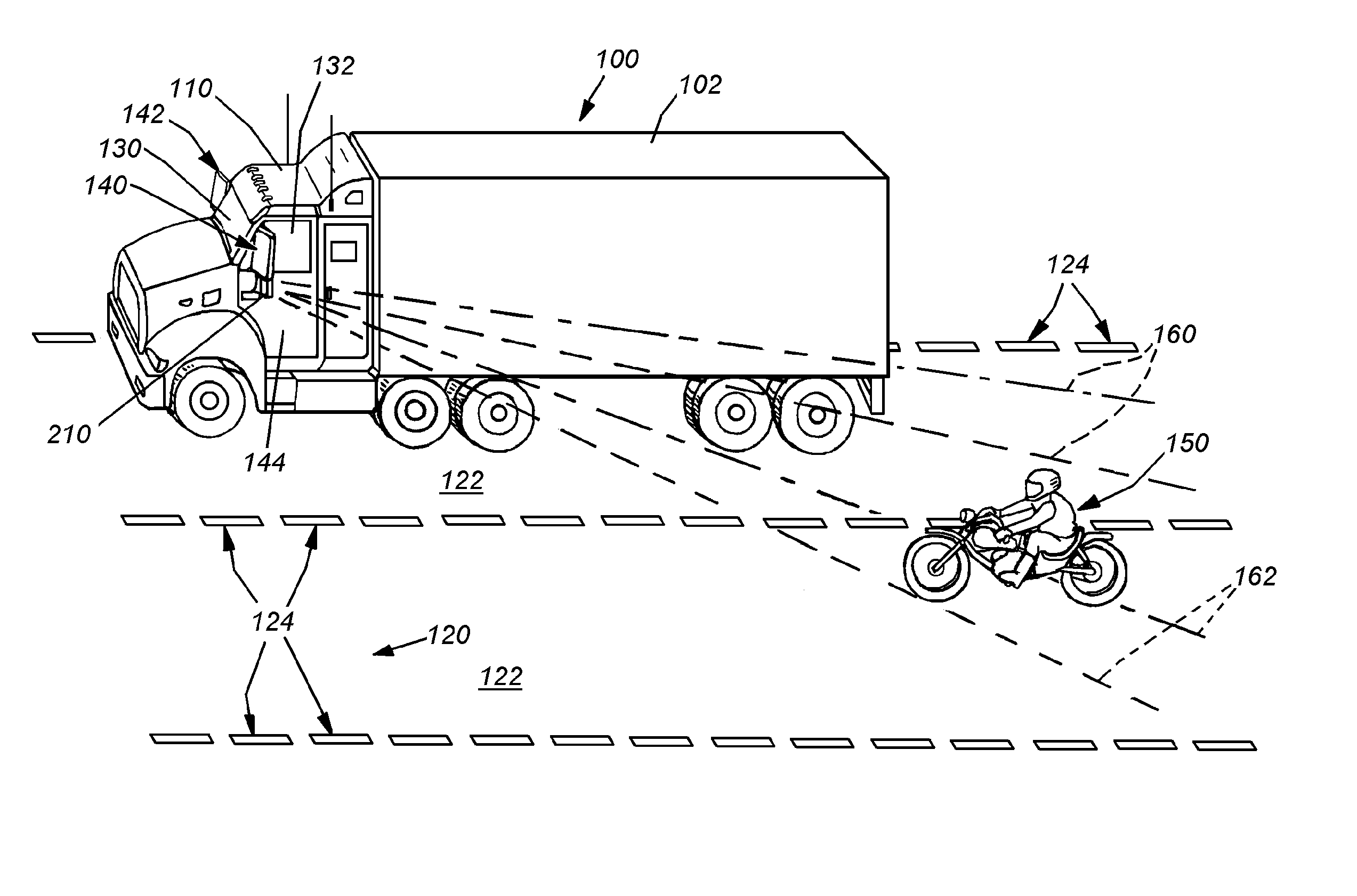
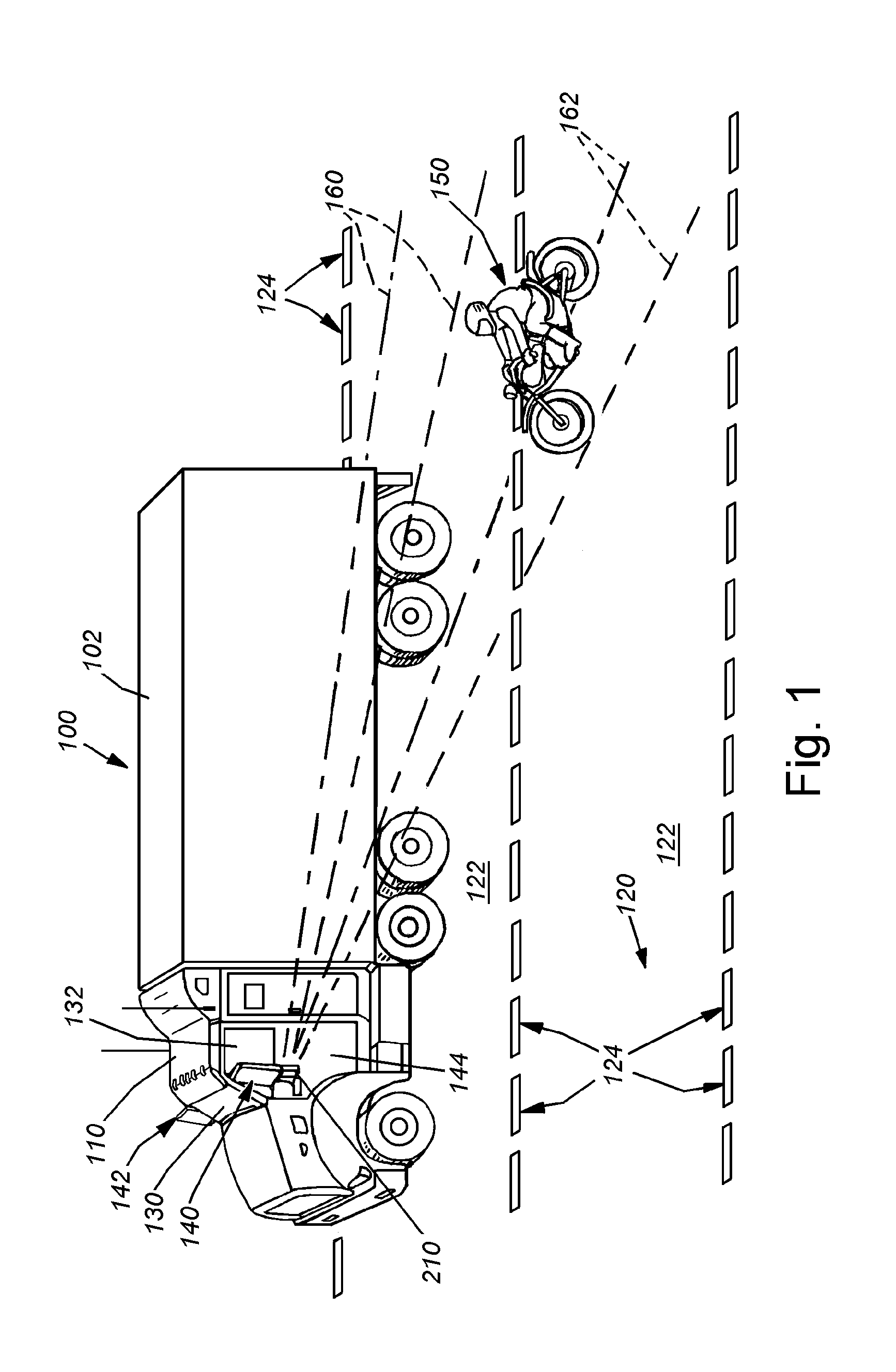
[0028]FIG. 1 shows an obstacle detection and collision-avoidance system mounted on an exemplary tractor trailer 100. The tractor trailer (also part of a class of large cargo vehicles termed generally herein as a “truck”) 100 includes a box trailer 102 and a cab 110. The cab 110 houses the driver and provides the motive power for the rig. The driver is mounted relatively high in the cab 110 above the road surface 120, which consists of a plurality of highway lanes 122, separated by dividing lines 124. The cab windshield 130 affords the driver good visibility of the road ahead at long, medium and somewhat close distances. Likewise, the side windows 132 afford the driver a good view of obstacles and vehicles that are substantially aside the cab. Because rear view of the cab is occluded by the tall trailer 102, the driver relies upon large mirror assemblies 140, 142, which are horizontally spaced from the adjacent cab door (driver-side door 144 being shown in FIG. 1 and the passenger do...


PUM


Abstract

This invention provides a system and method for object detection and collision avoidance for objects and vehicles located behind the cab or front section of an elongated, and possibly tandem, vehicle. Through the use of narrow-baseline stereo vision that can be vertically oriented relative to the ground/road surface, the system and method can employ relatively inexpensive cameras, in a stereo relationship, on a low-profile mounting, to perform reliable detection with good range discrimination. The field of detection is sufficiently behind and aside the rear area to assure an adequate safety zone in most instances. Moreover, this system and method allows all equipment to be maintained on the cab of a tandem vehicle, rather than the interchangeable, and more-prone-to-damage cargo section and/or trailer. One or more cameras can be mounted on, or within, the mirror on each side, on aerodynamic fairings or other exposed locations of the vehicle. Image signals received from each camera can be conditioned before they are matched and compared for disparities viewed above the ground surface, and according to predetermined disparity criteria.

Description

RELATED APPLICATIONS[0001]This application claims the benefit of U.S. Provisional Application Ser. No. 60 / 869,681, filed Dec. 12, 2006, entitled STEREO VISION SYSTEM FOR SIDE VISION DETECTION OF OBSTACLES FOR VEHICLES, the entire disclosure of which is herein incorporated by reference.STATEMENT REGARDING FEDERALLY SPONSORED RESEARCH OR DEVELOPMENT[0002]This invention was made with U.S. government support under U.S. Department of Transportation National Highway Traffic Safety Administration Cooperative Agreement Numbers DTNH22-05-H-01232 and DTFH61-01-X-00053. The government has certain rights in this invention.FIELD OF THE INVENTION[0003]This invention relates to machine vision systems, and more particularly to vehicle-borne methods and apparatuses for detecting obstacles and potential colliding objects.BACKGROUND OF THE INVENTION[0004]To improve safety of our roads a number of safety systems for automobiles have been developed, which entail a variety of differing approaches to the ...

Claims


Application Information

Patent Timeline
IPC IPC(8): G06K9/00H04N7/18H04N13/239
CPCB60R1/00B60R1/12B60R11/04B60R2001/1253B60R2011/004B60R2300/107B60R2300/30B60R2300/804B60R2300/8066G06T7/0075G06T2207/10012G06T2207/30261G08G1/16H04N5/247H04N7/18H04N13/0239H04N2013/0074G08G1/166G08G1/167G06T7/593H04N13/239H04N23/90
Inventor POMERLEAU, DEAN ARTHURGOWDY, JAY W.TROUP, MATTHEWNICHANI, SANJAY
Owner COGNEX CORP
Why Eureka
Try Eureka