Electro-optical device, metal frame for electro-optical device, manufacturing method of electro-optical device, manufacturing method of metal frame for electro-optical device, and electronic apparatus

a manufacturing method and electrooptical technology, applied in the direction of electrical apparatus casings/cabinets/drawers, instruments, paper/cardboard articles, etc., to achieve the effect of sufficient mechanical strength, increased strength of side walls, and increased strength of metal frames

Active Publication Date: 2009-01-01
JAPAN DISPLAY WEST
View PDF13 Cites 57 Cited by
  • Summary
  • Abstract
  • Description
  • Claims
  • Application Information

AI Technical Summary

Benefits of technology

[0040]Since the metal frame for electro-optical device according to the above aspect of the invention has a folding portion at a distal end portion of at least a portion of the side walls, it is possible to increase the strength of the side walls. Moreover, since the side walls having the folding portion are connected in a seamless curved shape, the metal frame can have a strength corresponding to the combined strengths of the folding portions, and the strength of the metal frame can be

Problems solved by technology

The deformation of the metal frame appearing in any directions may ap

Method used


Image

  • Electro-optical device, metal frame for electro-optical device, manufacturing method of electro-optical device, manufacturing method of metal frame for electro-optical device, and electronic apparatus
  • Electro-optical device, metal frame for electro-optical device, manufacturing method of electro-optical device, manufacturing method of metal frame for electro-optical device, and electronic apparatus
  • Electro-optical device, metal frame for electro-optical device, manufacturing method of electro-optical device, manufacturing method of metal frame for electro-optical device, and electronic apparatus

Examples


first embodiment

of Method and Apparatus for Manufacturing Metal Frame for Electro-Optical Device

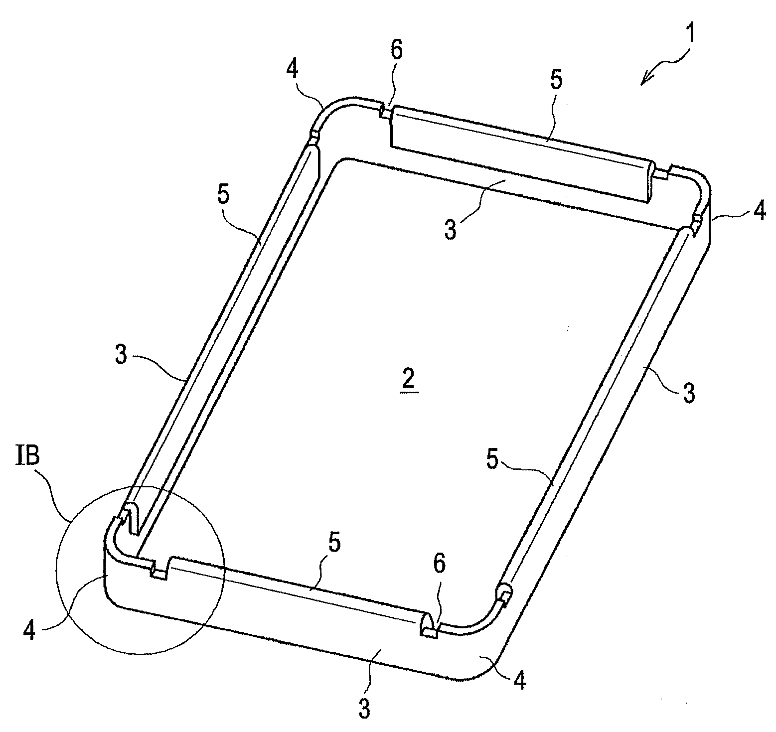
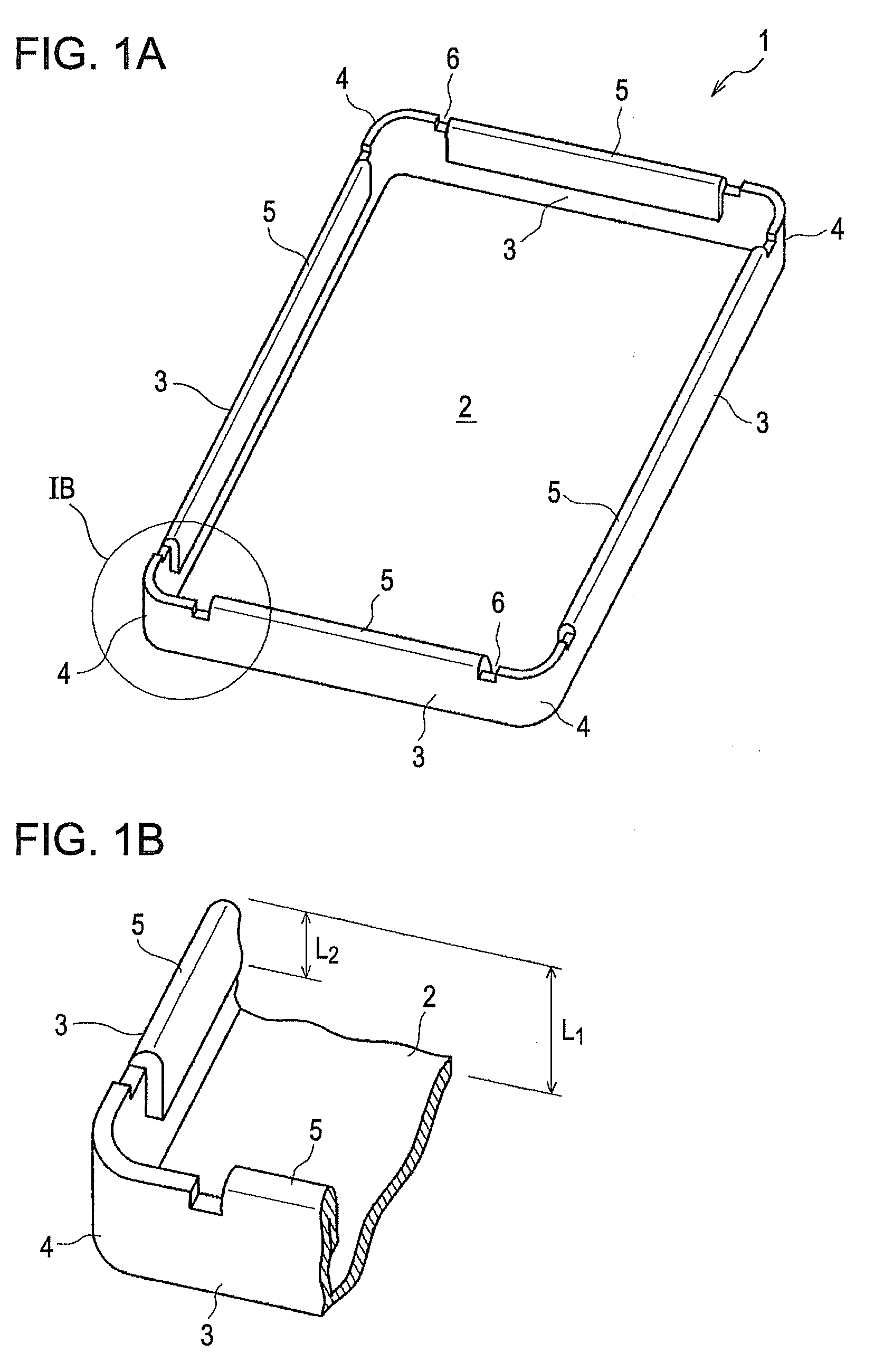
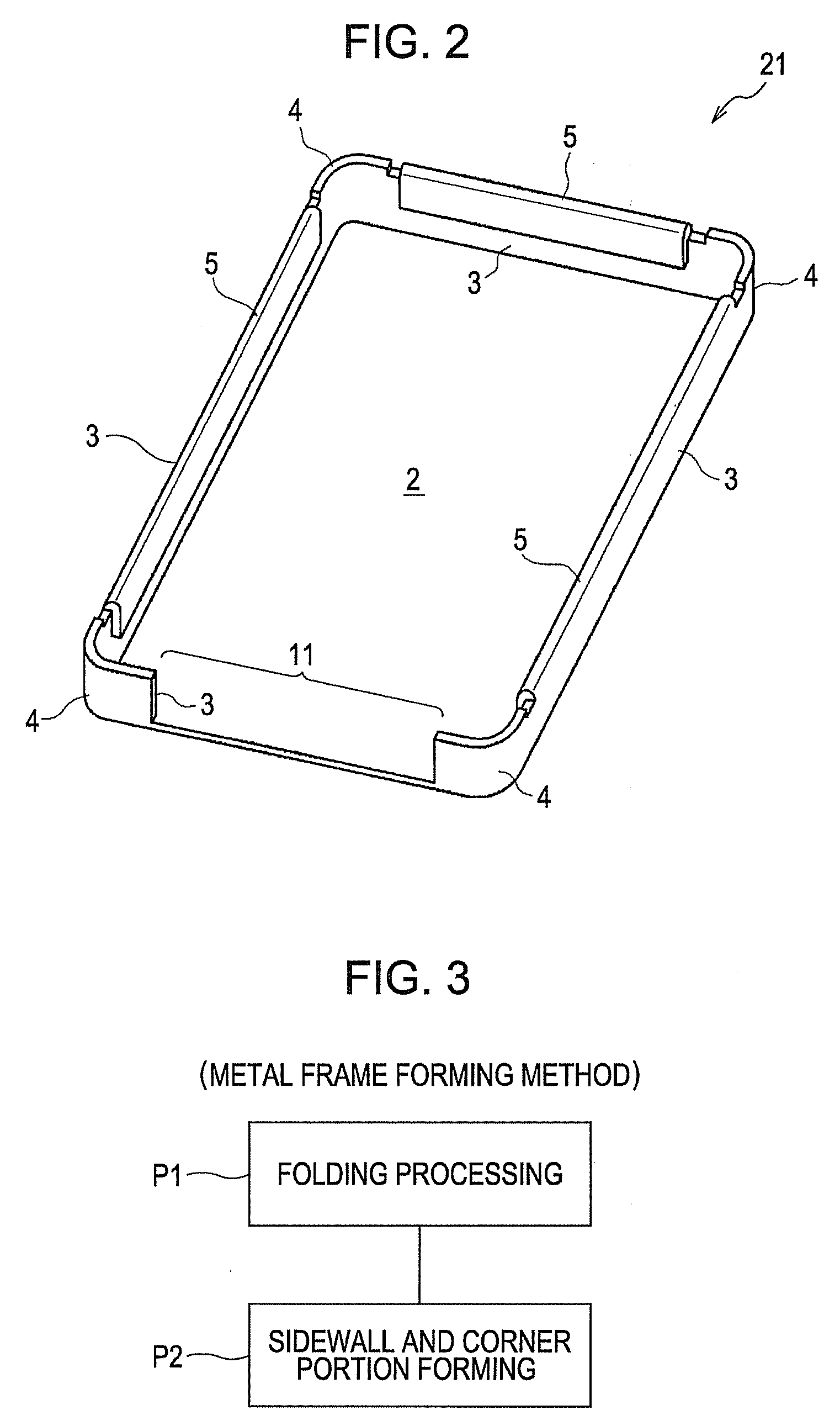
[0072]Next, a manufacturing method of the metal frame 1 for electro-optical device shown in FIG. 1 and a manufacturing apparatus for actualizing the manufacturing method will be described.

[0073]FIG. 3 is a diagram showing the process steps of a manufacturing method of a metal frame for electro-optical device according to the present embodiment. FIGS. 4 to 6 show the manufacturing procedures until the SUS steel plate is formed into a metal frame. Specifically, FIGS. 4A to 4C are development views of the steel plate, FIGS. 5A to 5C show the states where the folding portions are formed, and FIGS. 6A to 6C show the states of the finished metal frame. In the drawings, FIGS. 4A, 5A, and 6A are plan views, FIGS. 4B, 4C, 6B, and 6C are sectional views, and FIGS. 5B and 5C are side sectional views.

[0074]The manufacturing method of the metal frame for electro-optical device according to the present embodiment incl...

second embodiment

of Method and Apparatus for Manufacturing Metal Frame for Electro-Optical Device

[0085]Hereinafter, a method and apparatus for manufacturing a metal frame for electro-optical device according to another embodiment will be described.

[0086]FIGS. 11A to 11C show the principal parts of the method and apparatus for manufacturing the metal frame for electro-optical device according to the present embodiment. In this manufacturing apparatus, the inner metal mold includes four movable molds 34 that are arranged on the diagonal lines of the metal frame 1 and four auxiliary metal molds 35 that are arranged at positions opposite the side walls 3 of the metal frame 1. Each of the movable molds 34 has a right-angled block shape and is formed by a middle portion 34a of which the outer circumferential surface has a shape conforming to the shape of the inner circumferential surfaces of the corner portions 4 of the metal frame 1 in FIG. 1A and a pair of branch portions 34b of the same length that ext...


PUM


Abstract

An electro-optical device is provided which includes an electro-optical panel; and a metal frame configured to accommodate the electro-optical panel therein. The metal frame includes a plurality of side walls and corner portions provided between the side walls. A distal end of at least a portion of at least one of the side walls has a folding portion having a structure that inner surfaces are opposed to each other. At least one of the corner portions adjacent to the side wall having the folding portion has a seamless curved shape.

Description

BACKGROUND[0001]1. Technical Field[0002]The present invention relates to an electro-optical device, a metal frame for electro-optical device, a manufacturing method of an electro-optical device, a manufacturing method of a metal frame for electro-optical device, and an electronic apparatus[0003]2. Related Art[0004]In the past, as an electro-optical device manufactured using a metal frame, a display apparatus is known (for example, see page 4 and FIG. 2 of JP-A-2004-240239). In the display apparatus, a display panel is accommodated in the metal frame via a resin frame. The metal frame has its side surfaces that are usually folded vertical to a bottom surface in order to increase its strength against external load.[0005]In technical fields other than the display apparatus, the following technologies are known as a structure for reinforcing a box-shaped metal body. In page 2 and FIGS. 9 and 10 of JP-A-56-015107, a structure is disclosed in which end portions of steel material are folde...

Claims


Application Information

Patent Timeline
IPC IPC(8): B32B3/30
CPCG02F1/133308Y10T29/49002G02F2201/503G02F2001/133314G02F1/133314
Inventor NAKANISHI, DAISUKEONISHI, YASUNORIHASHINO, NARUO
Owner JAPAN DISPLAY WEST
Why Eureka
Try Eureka