Matrix converter apparatus

a matrix converter and apparatus technology, applied in the field of matrix converter apparatus, can solve the problems of inability to input current harmonics are considerable, and general matrix converter apparatus cannot deal with such a step up use, so as to reduce the current capacity of the semiconductor switching element, reduce surge voltage, and reduce the current flow of the bidirectional switch.

Active Publication Date: 2009-03-05
YASKAWA DENKI KK
View PDF6 Cites 27 Cited by
  • Summary
  • Abstract
  • Description
  • Claims
  • Application Information

AI Technical Summary

Benefits of technology

[0068]According to the invention, there is achieved an effect of capable of realizing the matrix converter apparatus capable of outputting the alternating current voltage of an arbitrary voltage / arbitrary frequency realizing to step up the output voltage by using the standard reactor, further, providing both of the step up outputting function and the step down outputting function, capable of dealing with outputting the step down voltage, outputting the step up voltage and the regenerating operation to the power source side by a single piece of the matrix converter apparatus, and capable of instantaneously switching the step up and step down operations even in the actual operation.
[0069]Further, in the step up operation, the rapid change of the current flowing in the bidirectional switch can be restrained, the surge voltage can be restrained from being brought about, and therefore, there is achieved an effect of capable of reducing a current capacity of the semiconductor switching element of the IGBT transistor or the like constituting the bidirectional switch and capable of preventing destruction of the semiconductor switching element.

Problems solved by technology

However, as a basic characteristic of the PWM converter, there is pointed out a disadvantage that a power source cannot be regenerated to a side of the alternating current power source and input current harmonics are considerable.
However, in this case, there poses a problem that a number of elements of IGBT and the like are doubled, further, a control apparatus of the PWM converter portion is also needed.
However, although it is necessary to supply an output voltage higher than the input power source voltage to a load side in accordance with use thereof, the general matrix converter apparatus cannot deal with such a step up use.

Method used


Image

  • Matrix converter apparatus
  • Matrix converter apparatus
  • Matrix converter apparatus

Examples


embodiment 1

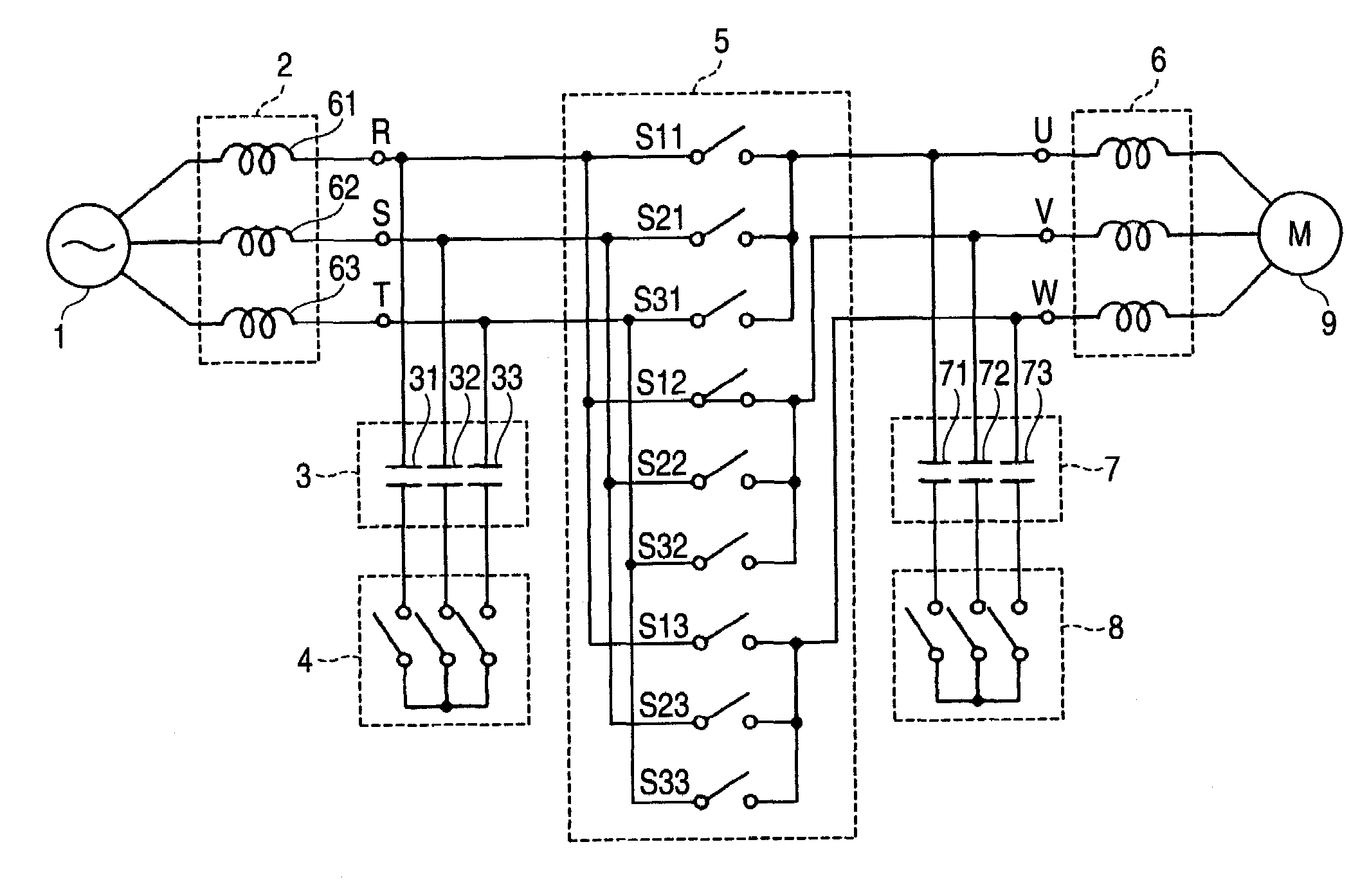
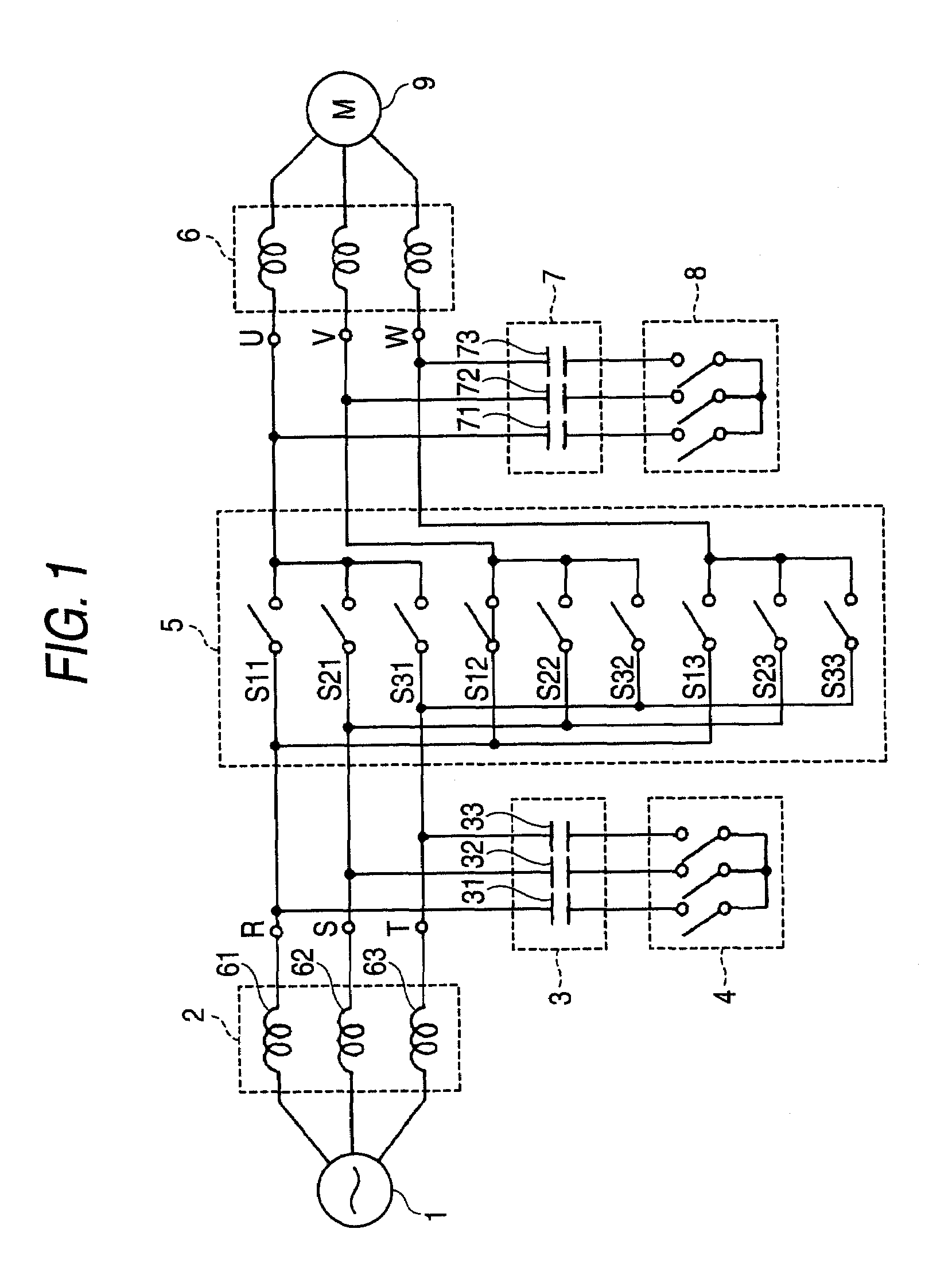
[0110]FIG. 1 shows a constitution of a matrix converter apparatus including the respective reactors 2 on an input side inserted to be connected between the three phase alternating current power source 1 and the bidirectional switch group 5 constituted by IGBT transistors or the like, the first capacitor group 7 for connecting respective phases on an output side, the first connecting / disconnecting means 8 capable of connecting / disconnecting connections among the respective capacitors constituting the first capacitor group 7, the second connecting / disconnecting means 4 capable of connecting / disconnecting connections among the respective capacitors constituting the second capacitor group 3, the respective reactors 6 on an output side inserted to be connected between respective phases on the output side and the motor 9, as a first embodiment of the invention.

[0111]Further, although in the embodiment of FIG. 1, the reactor 6 is inserted to be connected, a winding inductance provided to t...

embodiment 2

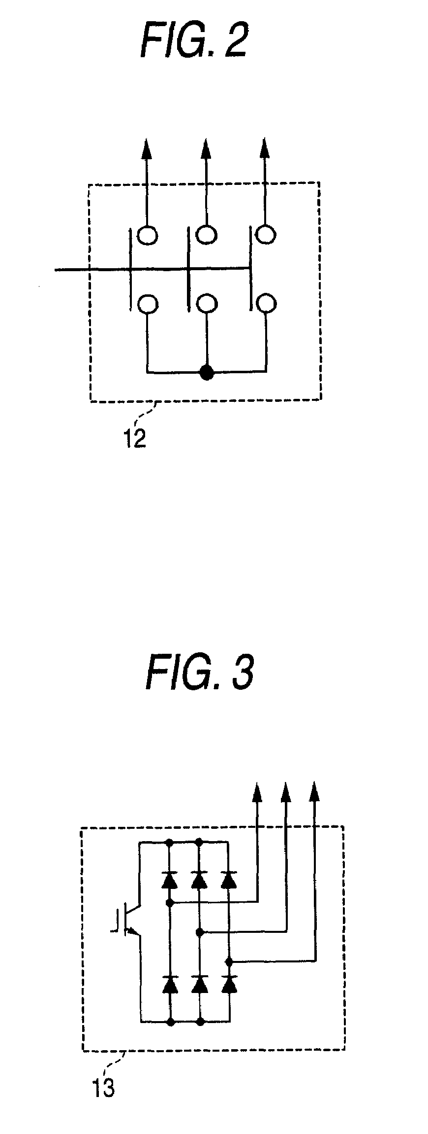
[0119]A second embodiment of the invention shown in FIG. 3 eliminates the above-described restriction by constituting the first, the second connecting / disconnecting means by an electronic type switch 13.

[0120]In FIG. 3, 6 diodes are connected to constitute a full-wave rectifying circuit and an IGBT transistor is connected across two positive and negative terminals of the full-wave rectifying circuit in parallel thereof. Regardless of any currents flowing in the first, the second capacitor groups, a current necessarily flows from a collector side to an emitter side of the IGBT transistor, and therefore, by making the IGBT transistor ON / OFF, the first, the second connecting / disconnecting means can be brought into a connected or a disconnected state.

[0121]Owing to the electronic type, a control mode can instantaneously be switched. For example, the control mode can instantaneously be switched immediately after making all of the bidirectional switches OFF, or when a snubber circuit is c...

embodiment 3

[0122]FIG. 4 shows a third embodiment of the invention. A direct current power source 10 is used in place of the three phase alternating current power source.

[0123]Similar to the first embodiment, by shortcircuitting the respective reactors on the input side by the bidirectional switches, the magnetic energy is increased to accumulate in the reactor, thereafter, the magnetic energy is discharged by making the bidirectional switches related to the shortcircuitting OFF, and the discharged magnetic energy is charged to the first capacitor group to thereby realize the step up voltage output. In the step down control mode, when brought into a regenerating operation state in which the power flows from the side of the motor 9, the power source can be regenerated from the matrix converter apparatus to the side of the direct current power source 10. When there are present two operation modes of a motor drive mode, the regenerating mode in actually operating the motor 9, the modes can fully b...


PUM


Abstract

There is provided a matrix converter apparatus including both functions of outputting a step up voltage and outputting a step down voltage. In a matrix converter apparatus for directly connecting respective phases of a three phase alternating current power source (1) and respective phases of an output side by a bidirectional switch constituted by IGBT transistors or the like connected reversely in parallel therewith, controlling to output an alternating current power source voltage by a PWM control based on an output voltage instruction, and outputting an arbitrary direct current or alternating current voltage, respective reactors (61), (62), (63) inserted to be connected between the respective phases of the polyphase alternating current power source 1 and the bidirectional switches are included, and by controlling to ON / OFF the bidirectional switches, terminals of two or more of the reactors on a side of the bidirectional switch are shortcircuited, and thereafter opened to thereby step up an output voltage of the matrix converter apparatus. Further, when the terminals are switched from being shortcircuited to being opened, conduction paths of currents flowing in the respective reactors which have been shortcircuited are ensured by controlling to ON / OFF the bidirectional switch group (5) and a capacitor group (7).

Description

TECHNICAL FIELD[0001]The present invention relates to a matrix converter apparatus for outputting an arbitrary polyphase alternating current or direct current voltage by constituting an input thereof by a polyphase alternating current power source, which is a matrix converter apparatus having a step up / step down function of the output voltage.RELATED ART[0002]A power converting apparatus generally signifies an apparatus of converting an alternating current power source voltage constituting a fixed voltage / a fixed frequency into a voltage / a frequency having arbitrary magnitudes. A currently most generally used power converting apparatus is a PWM inverter of a voltage source type. A PWM inverter subjects a direct current voltage provided by converting an alternating current power source voltage to PWM switching by using a high speed semiconductor switching element of IGBT or the like to output from alternating current voltage converted into an arbitrary voltage / frequency.[0003]However...

Claims


Application Information

Patent Timeline
Patent Type & Authority Applications(United States)
IPC IPC(8): H02M7/06
CPCH02M5/293H02M7/12
Inventor HARA, HIDENORIYAMAMOTO, EIJI
Owner YASKAWA DENKI KK
Why Eureka
Try Eureka