Cathode ray tube with improved mask assembly

a cathode ray tube and mask assembly technology, applied in the field of cathode ray tubes, can solve the problems of deteriorating color purity of the screen, and achieve the effect of reducing the width of the skirt portion

Inactive Publication Date: 2009-03-19
SAMSUNG SDI CO LTD
View PDF15 Cites 0 Cited by
  • Summary
  • Abstract
  • Description
  • Claims
  • Application Information

AI Technical Summary

Benefits of technology

[0010]The present invention is a cathode ray tube for improving a shape of a mask assembly, suppressing a doming phenomenon of the shadow mask, and minimizing deterioration of color purity of a screen that is caused by miss-landing electron beams.

Problems solved by technology

Due to the doming phenomenon, the electron beams are miss-landed since the positions of the beam guide holes and the phosphors are not matched, and therefore a color purity of a screen is deteriorated.

Method used


Image

  • Cathode ray tube with improved mask assembly
  • Cathode ray tube with improved mask assembly
  • Cathode ray tube with improved mask assembly

Examples


Embodiment Construction

[0026]The present invention will be described more fully hereinafter with reference to the accompanying drawings, in which exemplary embodiments of the invention are shown. As those skilled in the art would realize, the described embodiments may be modified in various different ways, all without departing from the spirit or scope of the present invention.

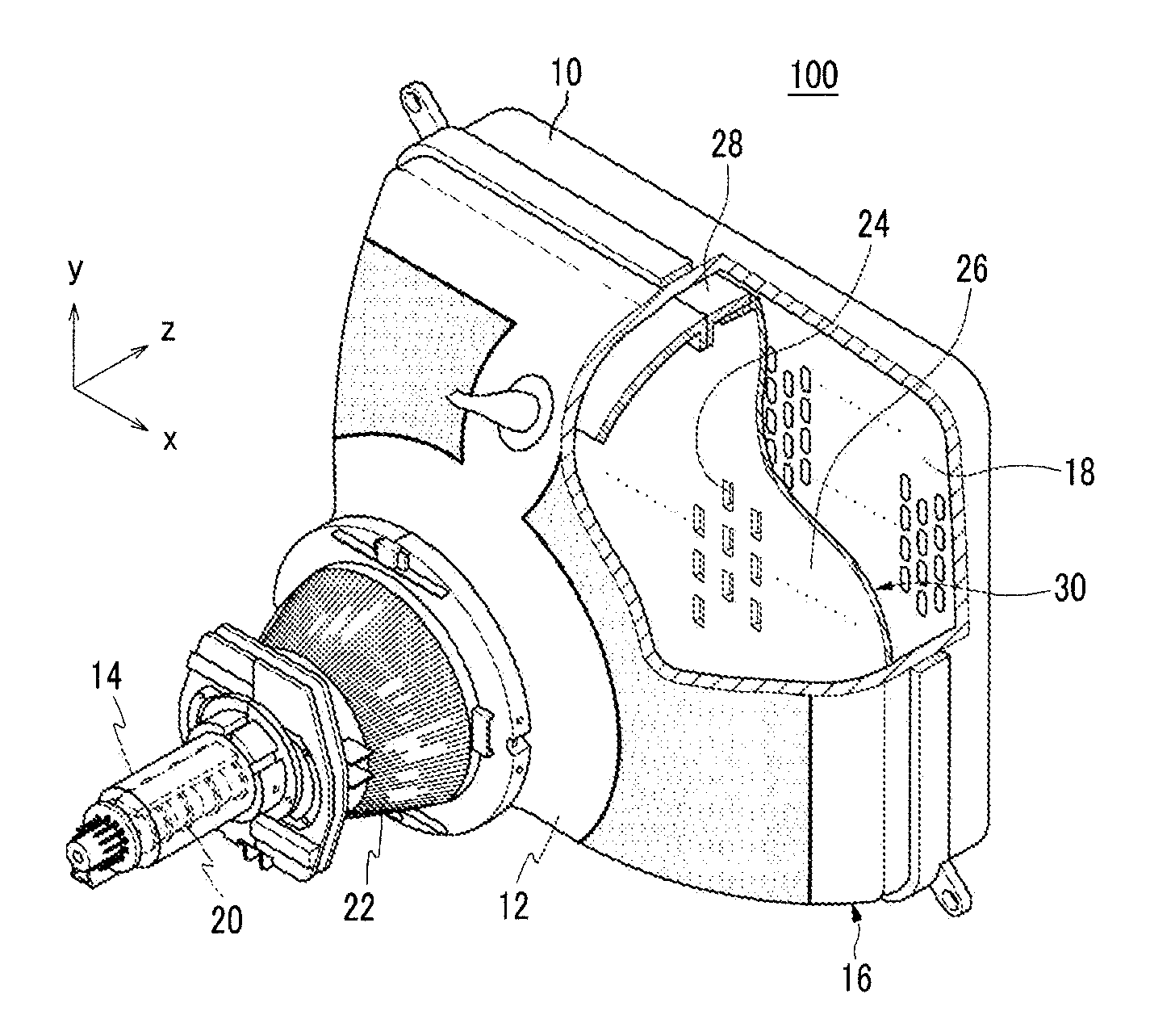
[0027]FIG. 1 is a partially cut-away perspective view of a cathode ray tube according to an exemplary embodiment of the present invention.

[0028]As shown in FIG. 1, a cathode ray tube 100 includes a vacuum tube 16 formed by integrating a panel 10, a funnel 12, and a neck 14. A fluorescence screen 18 including red, green, and blue phosphors is formed inside the panel 10, and an electron gun 20 for emitting three electron beams toward the fluorescence screen 18 is formed inside the neck 14. A deflection yoke 22 for generating a deflection magnetic field on the electron beam path to deflect the electron beams is formed outside the funne...


PUM


Abstract

A cathode ray tube including a shadow mask. The shadow mask includes an aperture portion including a plurality of beam guide holes, a non-aperture portion surrounding the aperture portion, and a skirt portion that is bent from an edge of the non-aperture portion toward an electron gun. The non-aperture portion includes a pair of longer sides, a pair of shorter sides, and four corner portions, and a first width of the non-aperture portion measured at the longer side and a second width of the non-aperture portion measured at the shorter side are formed to be less than a third width of the non-aperture portion measured at the corner portions. The shadow mask satisfies the following conditions: 2 mm≦w1<w3, and 2 mm≦w2<w3, where w1 denotes the first width of the non-aperture portion, w2 denotes the second width of the non-aperture portion, and w3 denotes the third width of the non-aperture portion.

Description

CROSS-REFERENCE TO RELATED APPLICATION[0001]This application claims priority to and the benefit of Korean Patent Application No. 10-2007-0093150 filed in the Korean Intellectual Property Office on Sep. 13, 2007, the entire content of which is incorporated herein by reference.BACKGROUND OF THE INVENTION[0002](a) Field of the Invention[0003]The present invention relates to a cathode ray tube. More particularly, the present invention relates to an improved mask assembly for a cathode ray tube.[0004](b) Description of the Related Art[0005]Usually, in a cathode ray tube, three electron beams emitted from an electron gun are deflected by deflection magnetic field. The three electron beams are gathered in beam guide holes provided on a shadow mask. The beams flow through the beam guide holes to separately collide with red, green, and blue phosphors of a phosphor screen. The phosphor layers receiving the electron beams emit light to realize a predetermined color image.[0006]A mask assembly ...

Claims


Application Information

Patent Timeline
Patent Type & Authority Applications(United States)
IPC IPC(8): H01J29/80
CPCH01J2229/0788H01J29/076H01J3/02H01J29/70H01J23/06H01J29/861
Inventor YOUN, HAE-SUSUK, BONG-KYUNGHA, KUEN-DONGPYUN, DO-HUNLIM, JONG-HOONLEE, WON-BOK
Owner SAMSUNG SDI CO LTD
Why Eureka
Try Eureka