Electrical connector

a technology of electrical connectors and connectors, which is applied in the direction of coupling device connections, coupling parts engagement/disengagement, electrical apparatus, etc., can solve the problems of small flexibility of plastics, user's inability to easily insert memory cards into electrical connectors, and the fixing clasp cannot provide enough operation space for memory cards, etc., to achieve less operation space and easy insertion

Active Publication Date: 2009-04-09
LOTES
View PDF4 Cites 11 Cited by
  • Summary
  • Abstract
  • Description
  • Claims
  • Application Information

AI Technical Summary

Benefits of technology

[0009]A scope of the invention is to provide an electrical connector with less operation space in a horizontal

Problems solved by technology

However, a user needs to operate the two push-out devices of the electrical connector to pull or inert the memory card.
For the preceding reasons, a user does not easily insert the memory card into the electrical connector.
However, the flexibility of plastic is small, so the fixing clasp can not provide enough operation space for the memory card when it is pulled from or inserted into the electrical connector.
And the memory card can not be easily inserted in or pulled from the electrical connector.
Besides, the fixing clasp does not have a structure for clasping the memory card, so one side-end of the memory card can not be fixed firm

Method used


Image

  • Electrical connector
  • Electrical connector
  • Electrical connector

Examples


Embodiment Construction

[0037]The advantage and spirit of the invention may be understood by the following recitations together with the appended drawings.

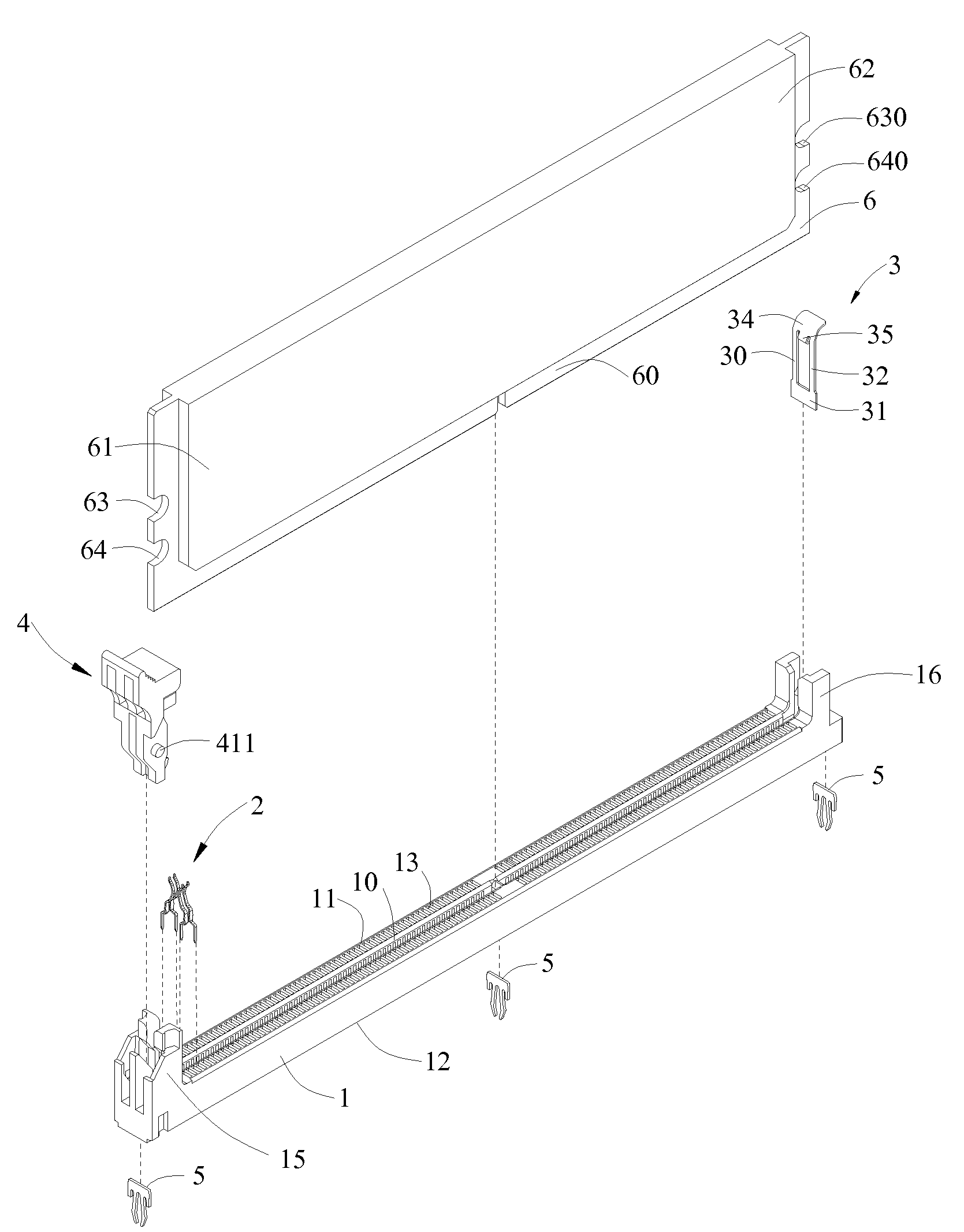
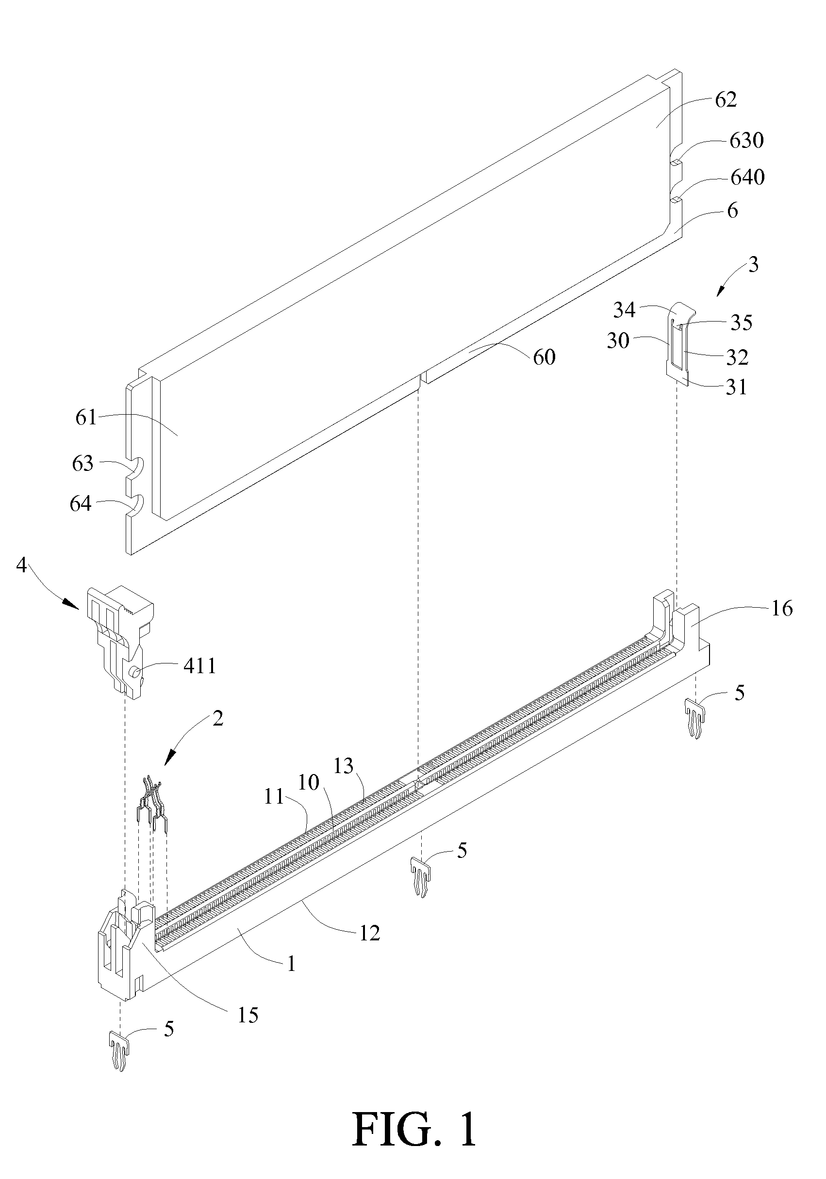
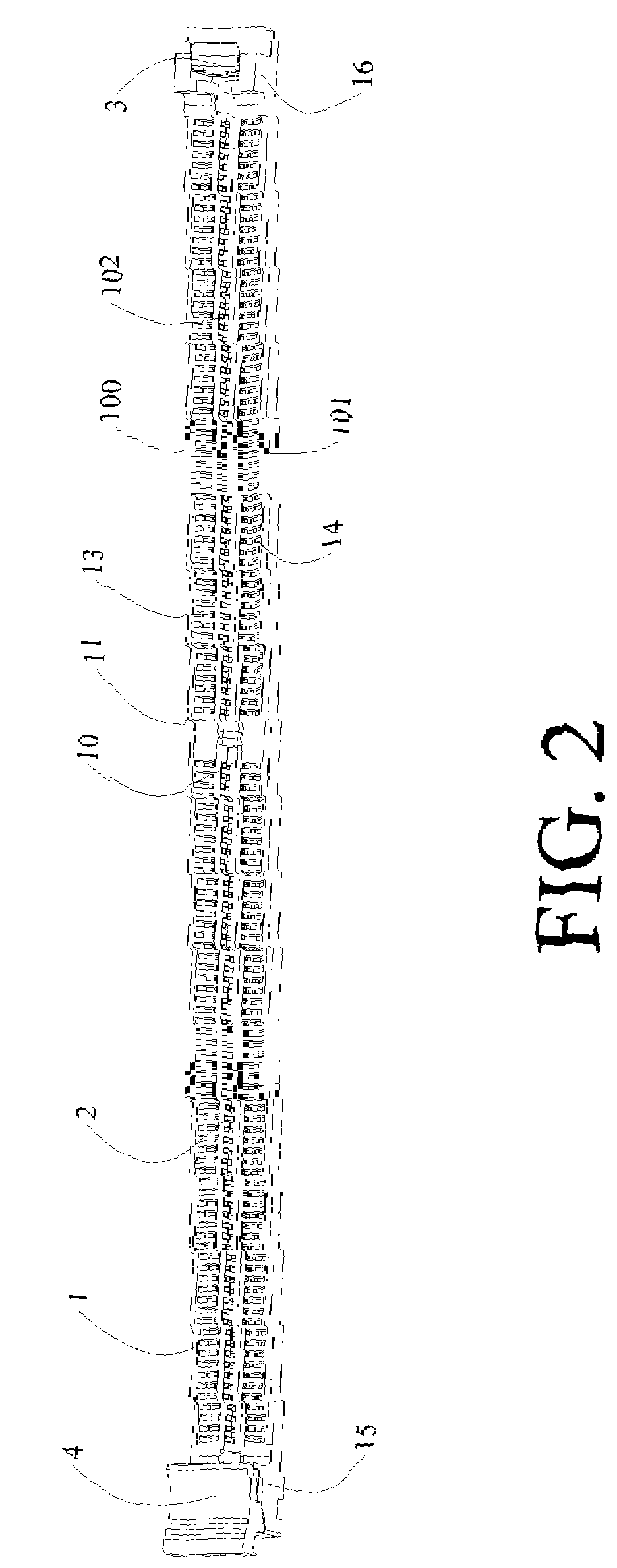
[0038]Please refer to FIG. 1 through FIG. 3. The electrical card 6 is electrically connected to a circuit board (not shown) via an electrical connector of the invention. The electrical connector of the invention includes an insulating body 1, a plurality of conducting terminals 2, an elastic body 3 disposed on the insulating body 1, a push-out device 4, and two fixing devices 5 for fixing the insulating body 1 onto the circuit board.

[0039]A slot 10 is used for inserting an electrical card in, and is disposed along a longitudinal direction of the insulating body 1. The insulating body 1 thereon defines a top surface 11 and a bottom surface 12 opposite to the top surface 11. There are multiple short slots 13 disposed on the top surface 11 and arranged on two sides of the slot 10. Two side-walls 100 and 101 of the slot 10 respectively include multiple holes...


PUM


Abstract

The invention relates to an electrical connector for inserting an electrical card in, and two side-ends of the electrical card respectively include at least one notch. The electrical connector includes an insulating body, a plurality of conducting terminals, a push-out device, and an elastic body. A top of the insulating body includes a slot and multiple accommodation chases along at least one side of the slot. The conducting terminals are disposed in the accommodation chases. The push-out device is pivotally engaged with a side-end of the insulating body, and includes a clasp part for clasping the notch of one of the side-ends of the electrical card. The elastic body is disposed on another side-end of the insulating body, and includes a main part, a fixing part for positioning the elastic body, and a buckle part for correspondingly buckling the notch of the other side-end of the electrical card.

Description

BACKGROUND OF THE INVENTION[0001]1. Field of the Invention[0002]The invention relates to an electrical connector.[0003]2. Description of the Prior Art[0004]So far, an insulating body of an electrical connector which is disposed on a motherboard and used for connecting a memory card has an inserting slot for inserting the memory card in. Two side-ends of the insulating body of the electrical connector respectively have a movable push-out device. However, a user needs to operate the two push-out devices of the electrical connector to pull or inert the memory card. Therefore, the operation needs more space for both hands, and the electrical connector needs more operation space in a horizontal direction. In general, an electrical connector for a display card is disposed perpendicular to the electrical connector for the memory card, so an end of the electrical connector for the display card is close to an end of the electrical connector for the memory card. Besides, the length of the dis...

Claims


Application Information

Patent Timeline
IPC IPC(8): H01R13/62
CPCH01R13/6275H01R12/716H01R13/6335H01R13/62966
Inventor JU, TED
Owner LOTES
Why Eureka
Try Eureka