
Hydroelectric Power Generation Device

Inactive Publication Date: 2014-03-20
CHEN TIEN CHUAN
View PDF7 Cites 3 Cited by
  • Summary
  • Abstract
  • Description
  • Claims
  • Application Information

AI Technical Summary

Benefits of technology

The present invention is a hydroelectric power generation device that uses solar energy to generate electricity without the need for high-temperature, high-pressure, and high-speed equipment. It includes a potential energy generation unit, a steam boiler, a solar water heater, a gravity transmission unit, and a generator set. Compared to traditional thermal power generations, the device is more environmentally friendly and requires less space. It also features better friendliness to surrounding environments and ecological systems.

Problems solved by technology

Each of these power generation methods has its own drawbacks, however.
For example, the thermal power generation may emit massive amount of carbon dioxides, leading to the concern of greenhouse effect.
Therefore, in accordance with the agreements on the Kyoto Protocol, the international community endeavors to achieve the goals of energy saving and carbon emission reductions, so the development of thermal power generations is quite restricted.
However, since human demands for electrical power keep increasing, the constructions of dams and reservoirs for power generation inevitably cause more valley tribes to be submerged under water because of water storage, resulting in agonies to mountain inhabitants and calamities for the natural environment, thus leading to extensive rejections to this type of power generation.
Moreover, due to climate changes, typhoons or storms may cause the dam or reservoir to be under the threat of landslides or silt sedimentations, all of which may undesirably reduce the performance of hydroelectric power generation.

Method used


Image

  • Hydroelectric Power Generation Device
  • Hydroelectric Power Generation Device
  • Hydroelectric Power Generation Device

Examples


Embodiment Construction

[0023]The embodiments of the present invention will now be set forth below in details, in conjunction with appended drawings and component symbols indicated therein, such that those skilled ones in the art can better appreciate the contents of the present invention for practice from reading the present disclosure.

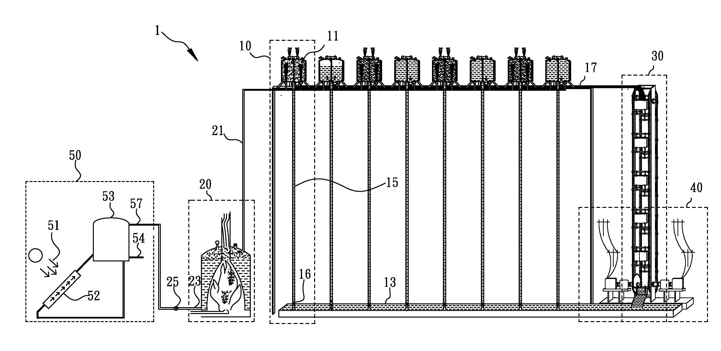
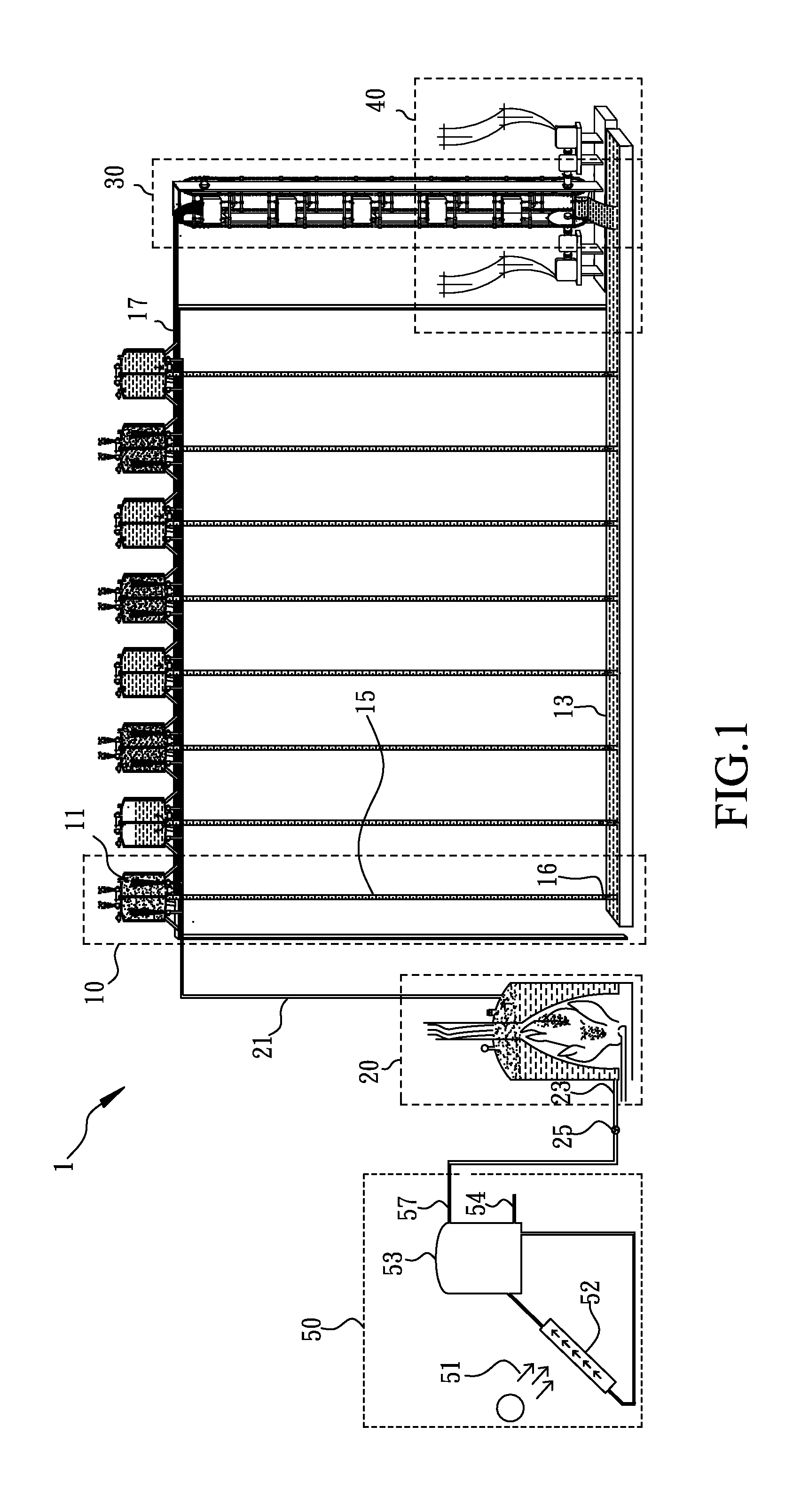
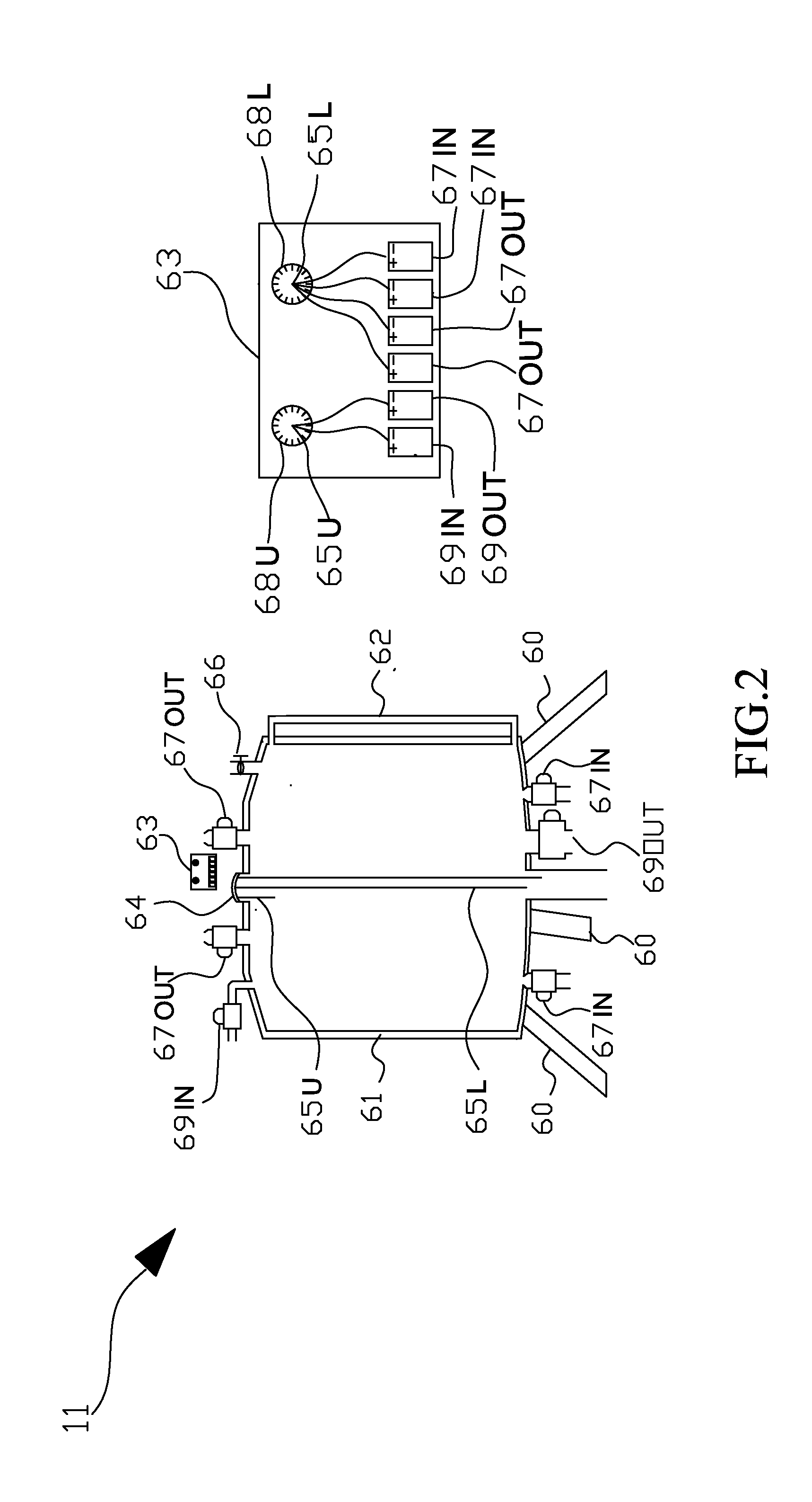
[0024]Refer first to FIG. 1, wherein a unit diagram of the hydroelectric power generation device according to the present invention is shown. In FIG. 1, it can be seen that the hydroelectric power generation device 1 according to the present invention comprises at least a potential energy generation unit 10, a steam boiler 20, a gravity transmission unit 30, a generator set 40 and a solar water heater 50. The potential energy generation unit 10 includes a control and load device 11, a withdrawal tank 13, a withdrawal pipe 15, a check valve 16 and a collection tank 17. The control and load device 11 is connected to the withdrawal tank 13 through the withdrawal pipe 15 for wa...


PUM


Abstract

A hydroelectric power generation device, comprises at least a potential energy generation unit including a control and load device, a withdrawal tank, a withdrawal pipe and a collection tank, where the control and load device acquires water from the withdrawal tank through the withdrawal pipe, and the collection tank is used to receive the water discharged from the control and load device; a steam boiler, acquiring hot water from a heat storage bucket of a solar water heater by way of a lower pipeline and generating steam, and then discharging steam to the control and load device via an upper pipeline; a gravity transmission unit, receiving water from the collection tank; and a generator set, converting the gravity introduced by the water in the collection tank into rotations thereby further generating electrical power.

Description

BACKGROUND OF THE INVENTION[0001]1. Field of the Invention[0002]The present invention relates to a hydroelectric power generation device, which applies solar energy, especially through cyclic water withdrawals, and converts into potential energy thereby driving electrical power generators through gravity transmissions for power generations.[0003]2. Description of Related Art[0004]The progress of modern life promotes higher and higher demands on electrical power. At present, common power generation approaches include thermal power generations by means of such as coals, gases or heavy oils, nuclear power generations through nuclear fissions, hydroelectric power generations based on conversions of potential energy from reservoir water level releases, as well as wind power generations, solar power generations and so forth.[0005]Each of these power generation methods has its own drawbacks, however. For example, the thermal power generation may emit massive amount of carbon dioxides, lead...

Claims


Application Information

Patent Timeline
IPC IPC(8): F02B73/00
CPCF01K27/005F03B7/006F03B17/005Y02E10/20
Inventor CHEN, TIEN-CHUAN
Owner CHEN TIEN CHUAN
Learn More