Power Wrench

a technology of power wrenches and wrenches, which is applied in the direction of wrenches, power driven tools, screwdrivers, etc., can solve the problems of safety risk, accidents, and apparatuses with retaining latch systems that may become twisted

Active Publication Date: 2009-04-30
WAGNER VERMOGENSVERWALTUNGS GMBH & CO KG
View PDF2 Cites 0 Cited by
  • Summary
  • Abstract
  • Description
  • Claims
  • Application Information

AI Technical Summary

Benefits of technology

[0008]According to another aspect of the invention, the housing of a power wrench of the type mentioned above is provided with a frictionally retained rotatable index ring arranged concentrically with the drive shaft, the index ring having a centric window through which a mark on the output shaft is visible. Such an index ring

Problems solved by technology

This entails the disadvantage of a safety risk caused by unreliable retaining systems.
This means a risk of accidents.
Apparatuses with retaining latch systems may become twisted after the end moment has been reached and have to be detached tedi

Method used


Image

  • Power Wrench
  • Power Wrench
  • Power Wrench

Examples


Embodiment Construction

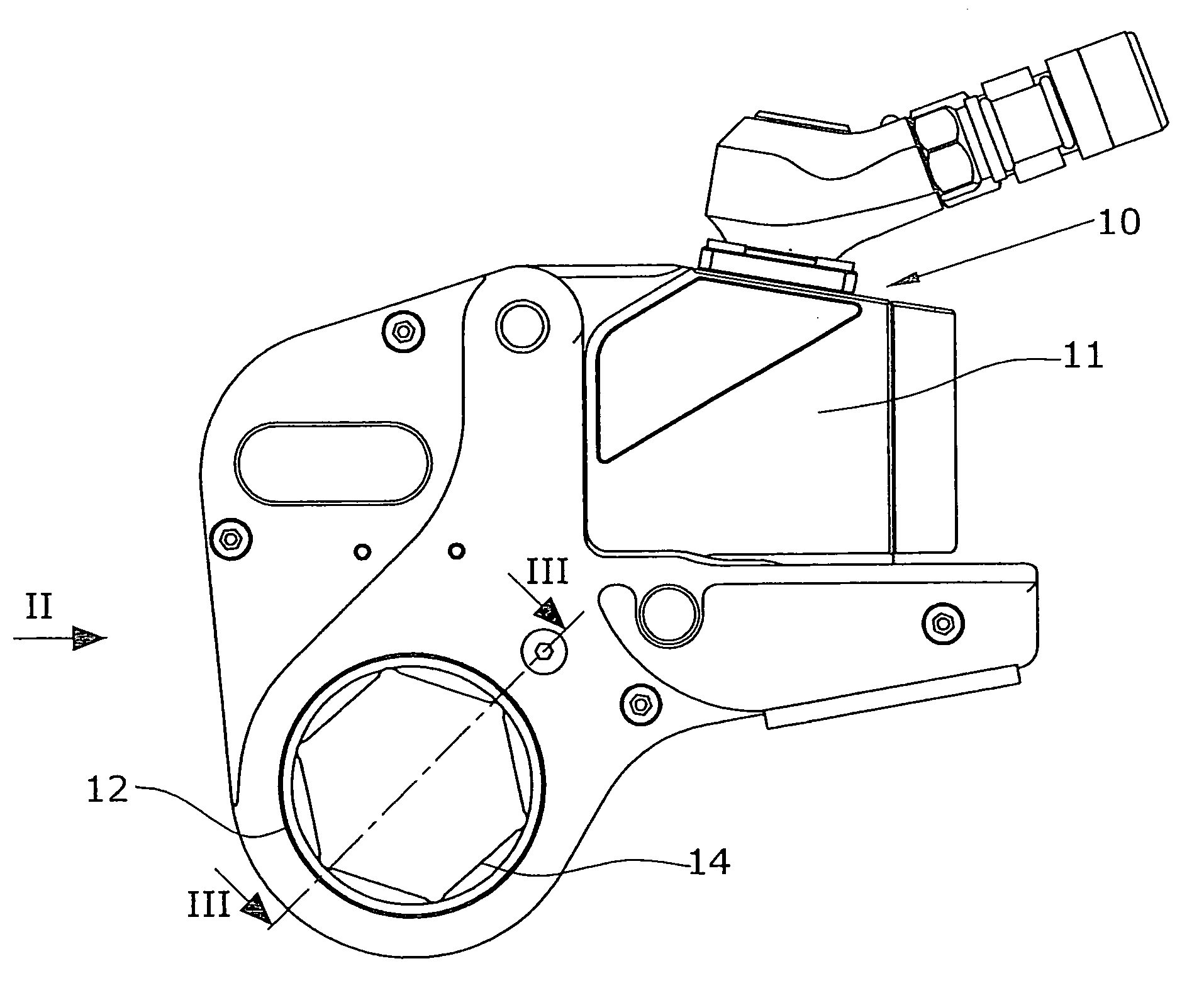
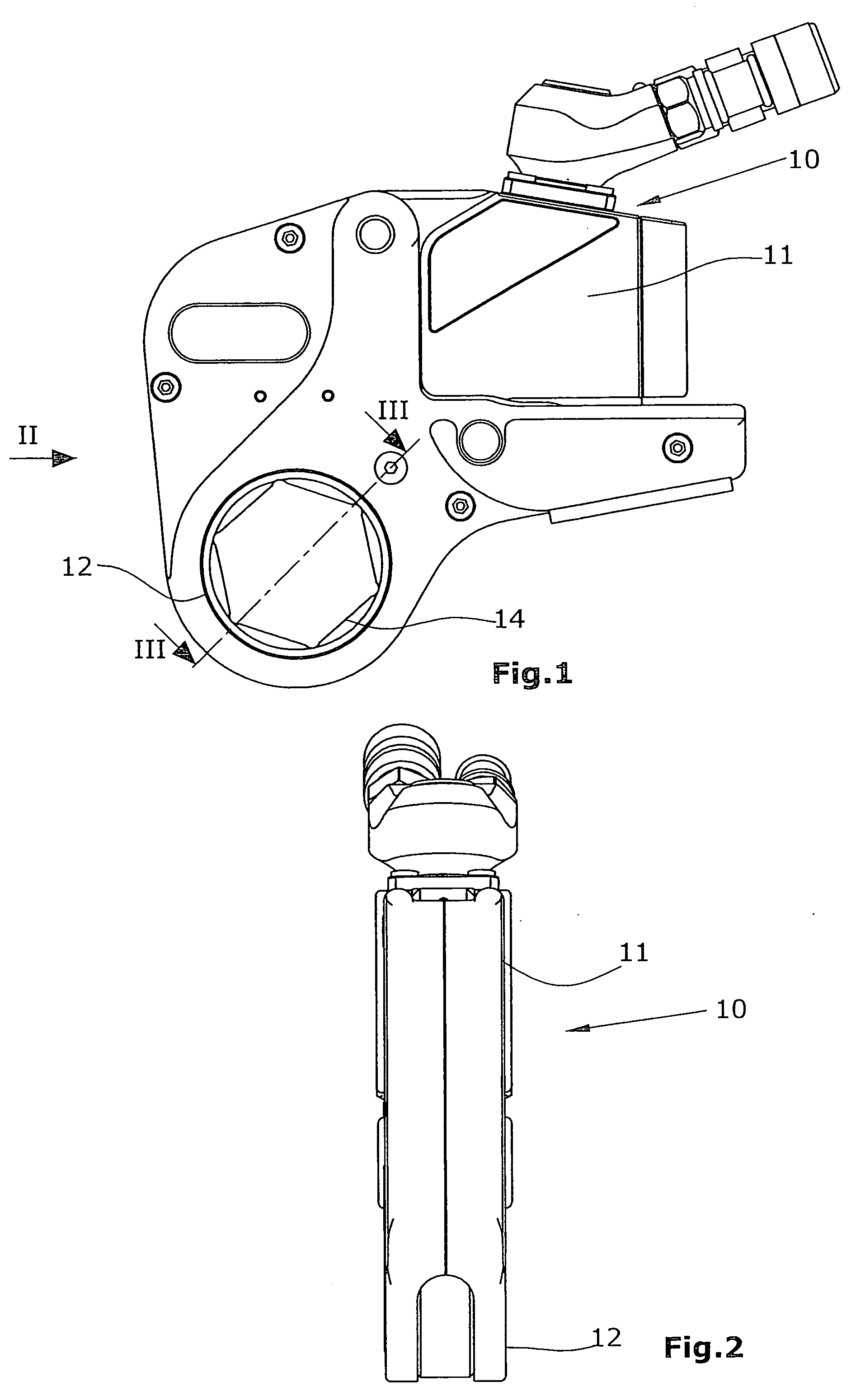
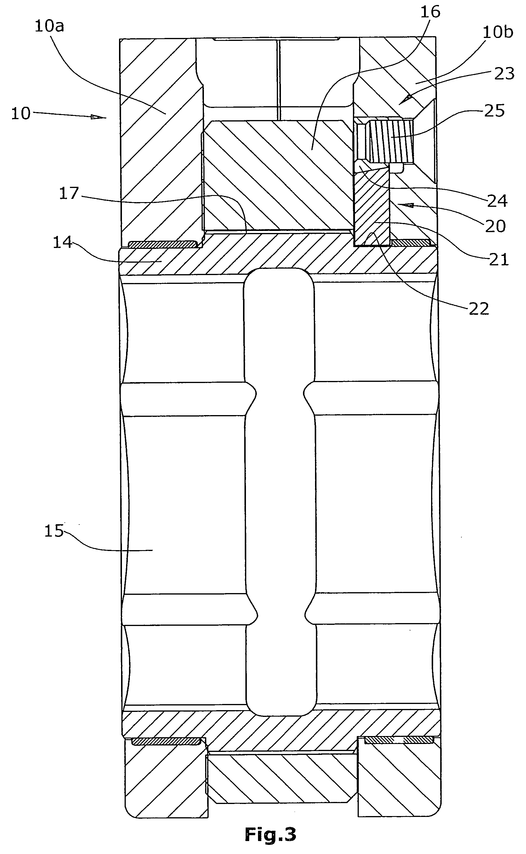
[0021]The power wrench of the embodiment illustrated in FIGS. 1-3 has a housing 1 of a substantially L-shaped design and accommodating a drive portion 11 in one leg and a driven portion 12 in the other leg. The drive portion includes a hydraulic piston / cylinder unit (not illustrated) with a reciprocating piston rod. The piston rod drives a ratchet lever. The driven portion 12 includes a output shaft 14 supported in the housing, the output shaft being a hollow shaft (FIG. 3) with an internal hexagon profile 15. Situated between two sidewalls 10A, 10B of the housing 10 is the ratchet lever 16 coupled with an outer toothing of the output shaft 14 via a toothing 17. In a working stroke, the ratchet lever 16 takes the output shaft 14 along in one rotational direction, whereas it slides back empty during the return stroke. In this manner, the output shaft 14 is rotated at intervals.

[0022]The friction brake 20 has a friction shoe 21 arranged radially with respect to the output shaft 14 and...


PUM


Abstract

The invention relates to a hydraulic power wrench comprising a ratchet lever (16) driven by a hydraulic cylinder. According to the invention, said power wrench is provided with a friction brake (20) which operates continuously between the housing (10) and the output shaft (14). In this way, reversed rotations of the output shaft following the individual working strokes are avoided.

Description

BACKGROUND OF THE INVENTION[0001]The invention refers to a power wrench with a drive portion including a hydraulic cylinder, and a driven portion, the driven portion comprising a output shaft rotatably supported in a housing and rotated at intervals by a ratchet lever.[0002]Hydraulic power wrenches are known that work based on the ratchet lever principle. When appropriately high hydraulic pressures are applied, such power wrenches can be used for very high torques. After a stroke of the hydraulic piston / cylinder unit, the output shaft tends to rotate backward by a small angle. This is due to the fact that the screw structure partly relaxes after each working stroke. To prevent such a relaxation, it is already known to have a blocking member engage the output shaft, the blocking member engaging an outer toothing of the output shaft, thereby preventing backward rotation. This entails the disadvantage of a safety risk caused by unreliable retaining systems. When the hydraulic unit that...

Claims


Application Information

Patent Timeline
IPC IPC(8): B25B21/00B25B13/46
CPCB25B21/005
Inventor WAGNER, PAUL-HEINZTHELEN, BERNDNIEMIETZ, ANDREASRUSSMANN, KLAUS
Owner WAGNER VERMOGENSVERWALTUNGS GMBH & CO KG
Why Eureka
Try Eureka