Switchgear

a switchgear and switch technology, applied in the field of switchgear, can solve the problems of ineffective structure to circulate air in the casing, easy dust pollution of high-voltage devices, and easy soiled high-voltage devices, etc., to achieve remarkable maintenance saving, easy flow out, and remarkable improvement of the reliability of the switchgear of the present invention

Inactive Publication Date: 2009-06-25
HITACHI LTD
View PDF8 Cites 14 Cited by
  • Summary
  • Abstract
  • Description
  • Claims
  • Application Information

AI Technical Summary

Benefits of technology

[0014]According to the present invention, the cables, connecting bars or bus bars and cable heads in the high voltage bus bar chamber are firmly insulated and protected from dust, moisture, salts, etc in the airflow. And, devices in the high voltage device chamber, such as circuit breakers are isolated substantially completely from dust, moisture, salts, etc. The airflow in the casing is formed by natural circulation by the action of upward airflow caused by heat generated in the heat generating components in the casing from the lower part of the casing toward the top portion of the casing, the dust, etc is easily flown out and heat is dissipated to outside the casing. Therefore, reliability of the switchgear of the present invention will be remarkably improved. As a result, the switchgear of the present invention is featured by low-cost, anti-dust structure and remarkable maintenance saving.

Problems solved by technology

However, this structure is not effective to circulate air in the casing.
The suction port may become an obstacle to the airflow.
However, the airflow that communicates with the suction port contains dust, etc and the high voltage devices may be easily soiled with the dust, etc.
Therefore, the cables, bus bars or cable heads may be soiled with dust, etc in the airflow.
This problem may arise from the technology disclosed in Japanese patent laid-open 2000-228803.
This structure, of course, makes large the switchgear size and increases a cost of the switchgear.

Method used


Image

  • Switchgear
  • Switchgear
  • Switchgear

Examples


Embodiment Construction

[0018]First of all, some of the features of the switchgear of the present invention will be listed and explained below. The switchgear of the present invention should have one or more features.

[0019]The switchgear of the present invention comprises:

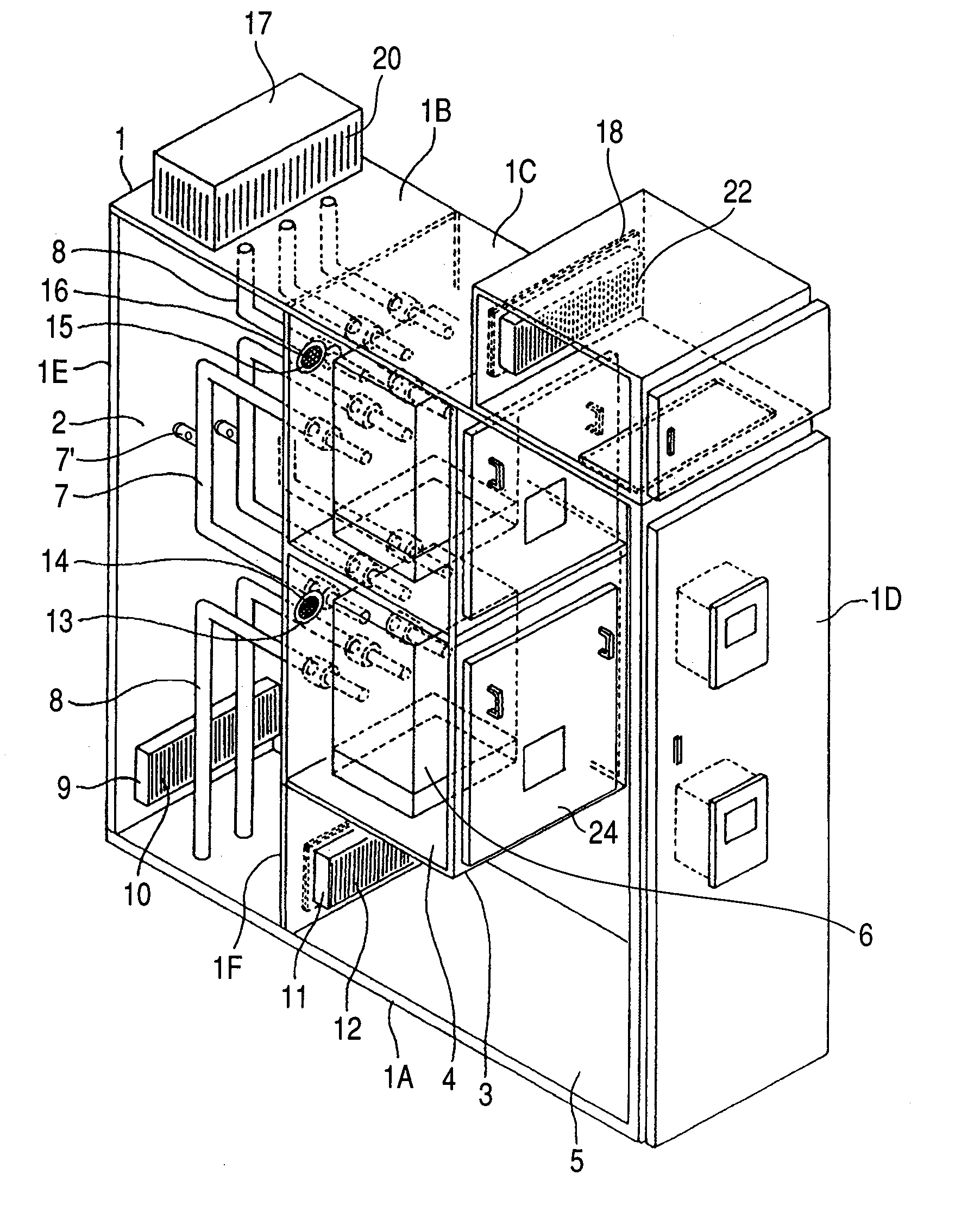
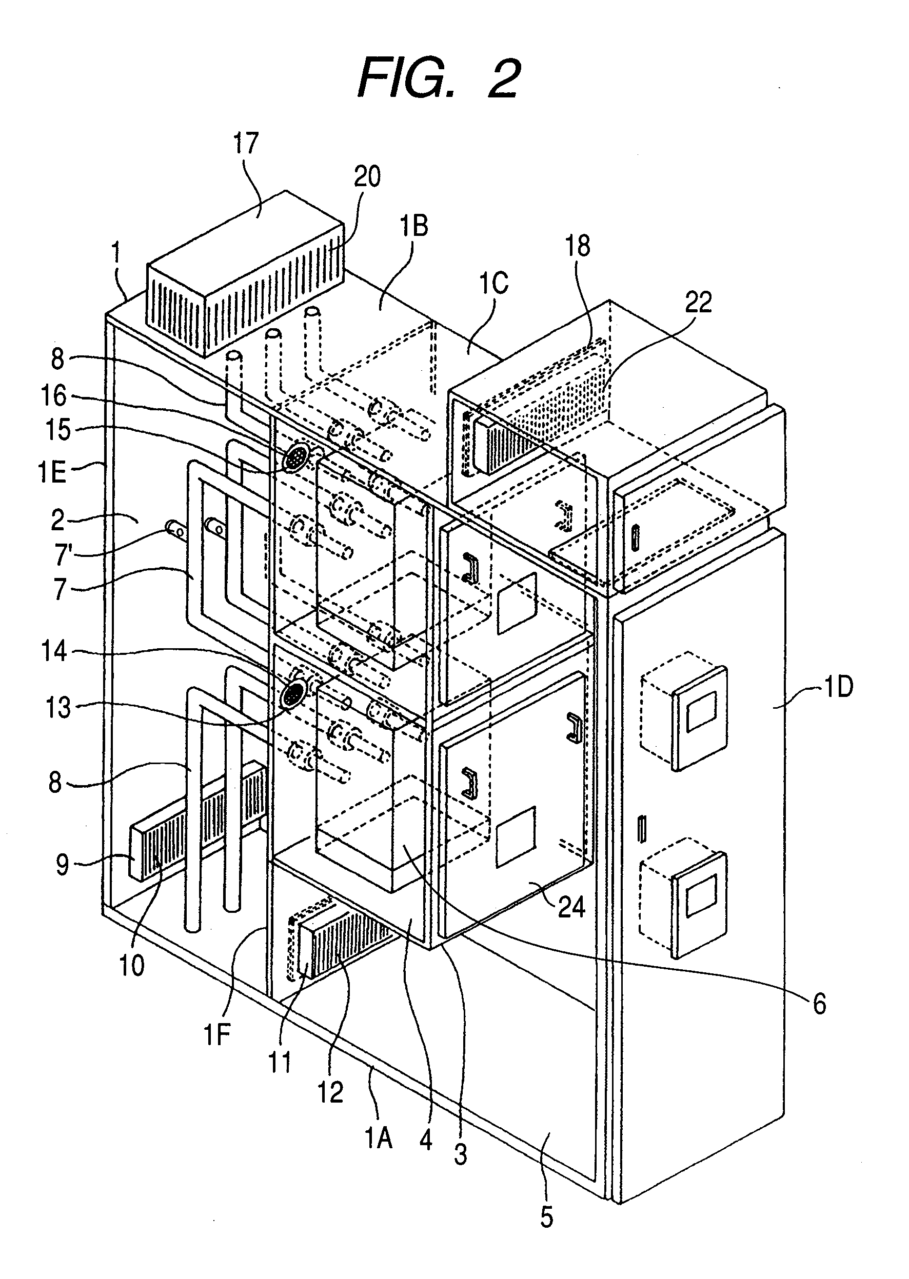
[0020](1) A casing partitioned into at least three chambers, i.e. a high voltage bus bar chamber, which contains at least bus bars and cable heads, a high voltage device chamber containing at least circuit breakers and a low voltage control chamber containing at least a relay and measurement devices. The casing should cover and protect the necessary components of the switchgear from environment.

[0021](2) The casing is constituted by a rear wall, a front wall opposed to the rear wall, a bottom wall, and a top wall opposed to the bottom wall, the rear wall having a first suction port disposed at a lower part thereof, the top wall having an exhaust port disposed above the high voltage bus bar chamber or in the top wall, wherein the high volt...


PUM


Abstract

A switchgear case is partitioned into a high voltage bus bar chamber, which contains bus bars and cable heads, a high voltage device chamber containing circuit breakers and operation mechanisms and a low voltage control chamber containing a relay and measurement devices, etc., A rear wall of the case has a first suction port disposed at a lower part thereof, wherein the high voltage bus bar chamber, high voltage device chamber and the low voltage control chamber are communicated and air passing through the chambers is discharged from a first discharging port of the casing. The bus bars electrically connecting the high voltage devices in the high voltage device chamber and connecting bars connecting the adjoining bus bars and the cable heads are covered with solid insulators for solid-insulation.

Description

CLAIM OF PRIORITY[0001]The present application claims priority from Japanese patent application serial No. 2007-325716, filed on Dec. 18, 2007, the content of which is hereby incorporated by reference into this application.THE FIELD OF THE INVENTION[0002]The present invention relates to a switchgear with improved dust prevention performance and maintenance saving.RELATED ART[0003]Switchgears generally comprises a casing enclosing a high voltage cable chamber containing at least bus-bars and cable heads, a high voltage device chamber containing at least two circuit breakers, and a low voltage control chamber containing at least measurement instruments and relays. The three chambers are substantially independent from each other, while the air for cooling the devices, etc. in the chambers is communicated and circulated towards an air discharging port. In the above switchgear there are various air circulation systems so as to keep clean the inside of the casing and to suppress temperatu...

Claims


Application Information

Patent Timeline
Patent Type & Authority Applications(United States)
IPC IPC(8): H01H33/02
CPCH02B13/01H02B1/56
Inventor KUROGI, TAKUYATSUCHIYA, KENJINAKATSUGAWA, NAOKIISHIKAWA, TAKUMIYAMADA, NOBUYUKI
Owner HITACHI LTD
Why Eureka
Try Eureka