Submersible electrical connector

a technology of electrical connectors and submersibles, applied in the direction of electrical connections, coupling device connections, electrical apparatus, etc., can solve the problems of affecting the operation of electrical connectors, so as to avoid the detailed and tedious cutting and sizing, and facilitate the use of a technician. , the effect of avoiding the loss of watertight plugs and plugs

Active Publication Date: 2009-07-09
ILSCO
View PDF48 Cites 11 Cited by
  • Summary
  • Abstract
  • Description
  • Claims
  • Application Information

AI Technical Summary

Benefits of technology

[0024]The electrical connector assembly also includes a plurality of wire way guide plugs each inserted into one of the ducts to seal the associated duct in the absence of a conductor in that duct. The wire way guide plugs can be generally missile-shaped, and each includes a detent to inhibit removal of the wire way guide plug from the duct in a retrograde direction. Each wire way guide plug contains an open end, antioxidant material inserted in the open end of the wire way guide plug to coat and protect the exposed ends of a conductor inserted into the wire way guide plug, and an end cap to cover the open end and protect the antioxidant material from contamination. Each wire way guide plug can be discarded or reused after a conductor is inserted into the wire way guide plug and through the duct to the connector plate.
[0025]As such, the submersible electrical connector of this invention is significantly more easily utilized by a technician even in a cramped and wet environment of an underground hand hole or the like. The invention avoids the detailed and tedious cutting and sizing required to use rockets or comparable plugs to effect a water-tight electrical connection. Moreover, the electrical connector accommodates a wide variety of conductor sizes and the installation and assembly of the conductors and electrical connector is readily inspected through the clear dome-shaped enclosure. Moreover, the connection system can be modified at any subsequent time to add or withdraw conductors without sacrificing the integrity of the water-tight connection. Finally, the problems associated with splayed strands of a conductor inserted through various ports, apertures and ducts is overcome with the wire way guide plug included in this invention.

Problems solved by technology

Problems, however, arise both where the conductors enter the case and more particularly where access to the set screw is required.
Since the technician often wears gloves, manual dexterity is compromised and the plug or rocket is often dropped.
One major cause of failure of this type of connector is the loss of watertight rockets and plugs.
The absence of a proper plug and a properly sized rocket allows water to penetrate the connector.
Unfortunately, water ingress, particularly where the plug and rocket is intended to seal against the jacket of the conductor end, may result in corrosion and failure of the connector.
When properly installed, such plugs and rockets do not permit water ingress.
Unfortunately, if improperly installed the seal provided by the plug and rocket may not be sufficient to keep water out.
Accordingly, water enters and degrades the electrical connection resulting in premature failure of the connector.
The inability to easily inspect the connectors in underground hand holes or vaults is also problematic, especially in light of the opportunity for errors in making the connections.
Instances of improper installation are more likely to occur as training and skill levels are reduced, and while at the same time greater production rates are required.
For example, an improperly trained technician may cut the rocket at a ring that is too large to correctly seal on the conductor.
Weeks, months or years after installation, water penetrates the area of the “seal” and causes connector failure.
Another problem associated with known electrical connectors of this type stems from the use of conductors having a number of strands encased in a plastic sheath.
Such frayed conductors with splayed strands are much more difficult for the technician to efficiently and cleanly insert into the connector to accomplish a proper connection.
Another problem associated with known electrical connectors of this type is ensuring a proper seal is created between the electrical connector and the enclosure, as any leakage in the wet environment leads to oxidation of connections and device failure.
A less highly-trained technician working on the electrical connector in darkness is especially susceptible to making mistakes when closing these devices, such as allowing contaminants to get into the seal surface.
Leaving the enclosure too loosely or too tightly connected to the electrical connector also frequently leads to failure of the seal.

Method used


Image

  • Submersible electrical connector
  • Submersible electrical connector
  • Submersible electrical connector

Examples


Embodiment Construction

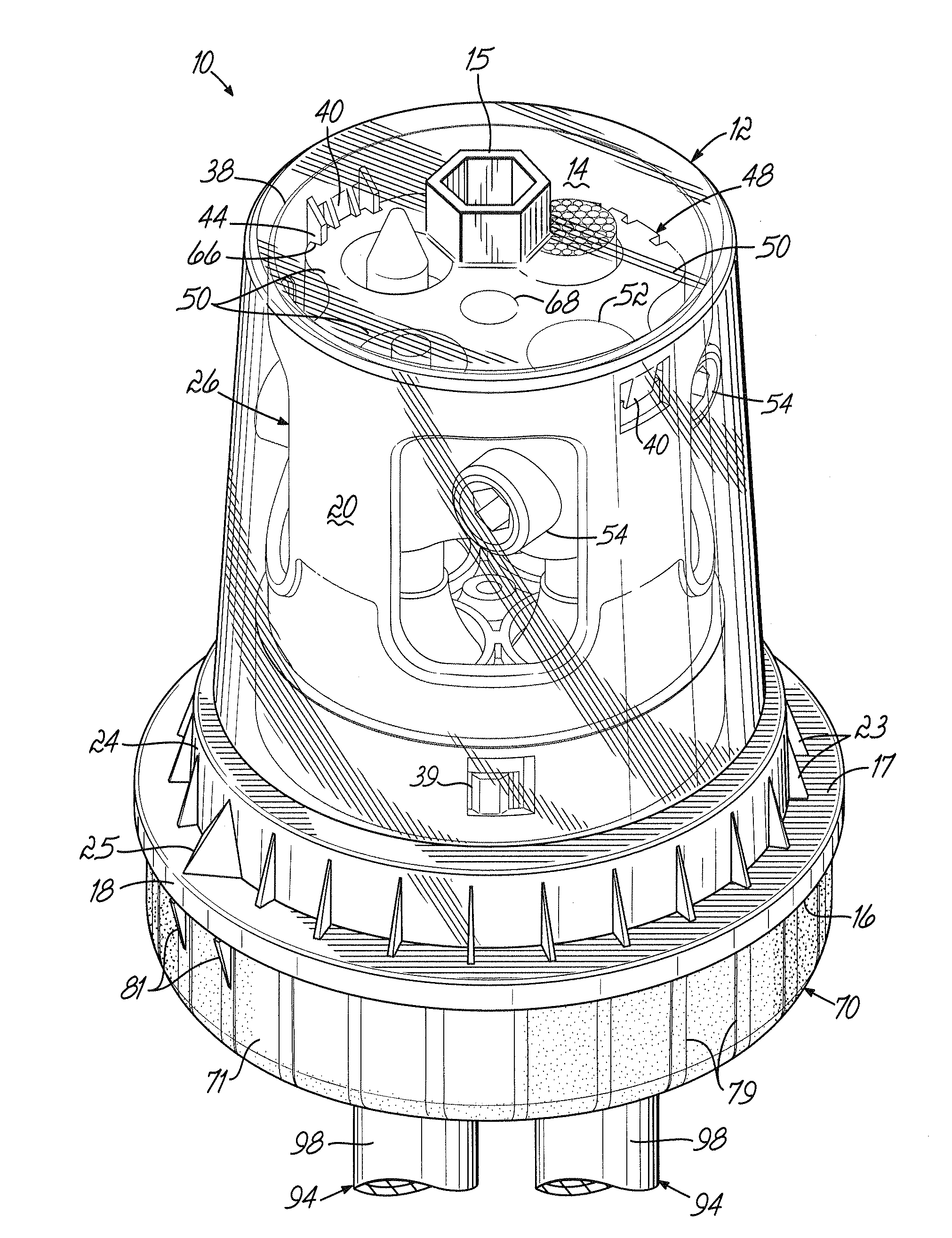
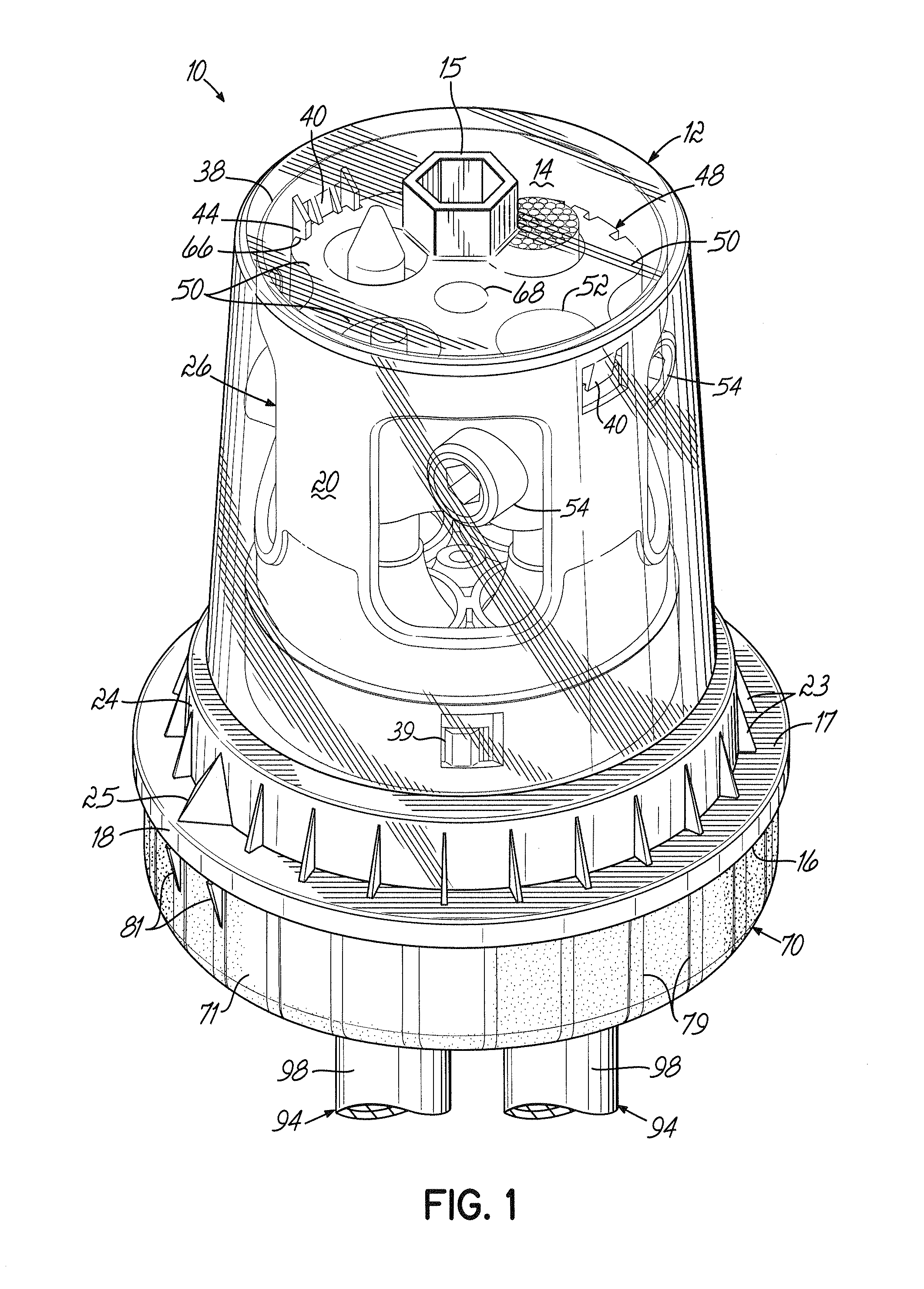
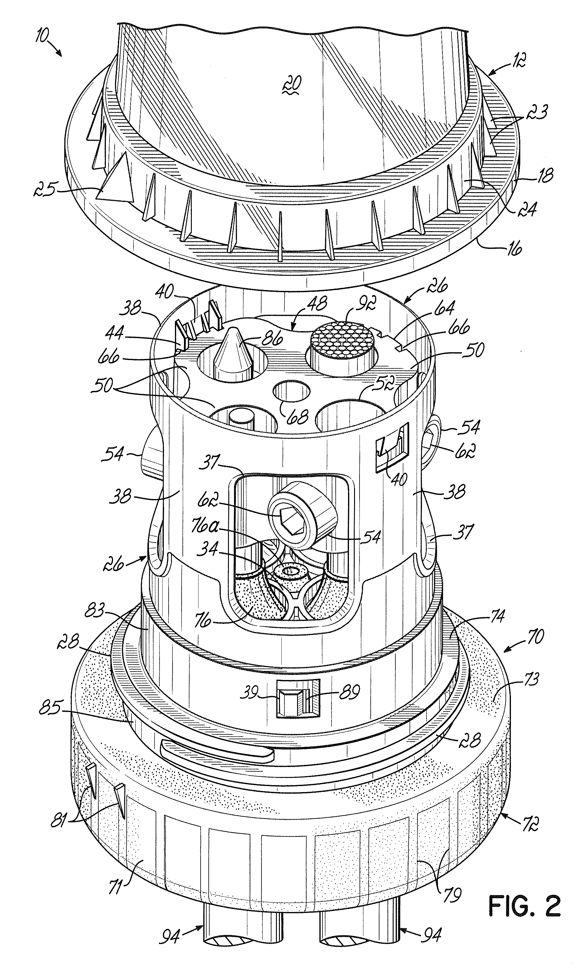
[0032]One exemplary embodiment demonstrating the various features and aspects of an electrical connector assembly 10 according to this invention is shown in FIGS. 1-2A and FIG. 4, and the installation of conductors and assembly of the electrical connector is shown in FIGS. 3A-3C.

[0033]The electrical connector assembly 10 of this invention includes a number of individual component parts and elements which will be described in detail with respect to FIGS. 1-2A. The electrical connector assembly 10 which is adapted to be submersible includes an enclosure 12 with a closed upper end 14 opposite from an open end 16 surrounded by a peripheral skirt 18. A generally cylindrical sidewall 20 of the enclosure 12 extends between the closed upper end 14 and the skirt 18. A tool adaptor 15 which is shown generally hexagonal projects outward from the closed upper end 14. The tool adaptor 15 helps make the installation and removal of the enclosure 12 easy for a technician. The peripheral skirt 18 co...


PUM


Abstract

A submersible electrical connector intended for use in a power distribution network permits a metal to stripped metal conductor connection to be visually inspected and verified by the installer while eliminating many opportunities for human error present with existing connectors. The connector in one embodiment includes a generally cup or dome-shaped enclosure which is preferably transparent. An open end of the enclosure mates with an upper seal body and a connector plate has a number of apertures adapted to receive the bare metal ends of conductors or wires inserted through the upper seal body. Each aperture in the connector has an associated set screw for securing the conductor thereto. A molded seal member is adapted to mate with the upper seal body and to provide a water-tight connection when mated with the enclosure. The seal member has a number of seal ducts each aligned with one of the apertures in the connector. The seal ducts provide a water-tight seal around the plastic sheath of the conductor when installed in the assembly. Each seal duct initially includes a missile-shaped wire way guide plug inserted therein. Each wire way guide plug can be opened at the bottom to receive the exposed end of the conductor therein. The wire way guide plugs remain installed in the seal ducts to seal them until a conductor is inserted through the associated seal duct.

Description

[0001]This is a continuation-in-part of PCT patent application Publication No. WO 2007 / 016072, which designates the U.S. and claims priority to U.S. application Ser. No. 11 / 192,564, filed Jul. 29, 2005, and issued as U.S. Pat. No. 7,229,325 on Jun. 12, 2007. Each of these patent properties is hereby incorporated by reference in its entirety.BACKGROUND OF THE INVENTION[0002]1. Field of the Invention[0003]This invention relates to the general field of electrical connectors and is particularly concerned with a submersible, set-screw type, electrical connector.[0004]2. Background of the Invention[0005]Electrical distribution systems are used extensively in most industrialized countries. These distribution systems typically include power cables, transformers and connectors for linking the components together. Some distribution systems have cables suspended from poles anchored into the ground so that the cables are located substantially above the ground surface. In such instances, the tra...

Claims


Application Information

Patent Timeline
Patent Type & Authority Applications(United States)
IPC IPC(8): H01R4/36
CPCH01R4/36H01R11/28H01R25/003H01R13/5216H01R13/5208
Inventor FLYNN, JEFFREY T.SMITH, WILLIAM E.WOLINS, BILL
Owner ILSCO
Why Eureka
Try Eureka