Body fluid sampling device and body fluid measuring device using the same

a body fluid and measuring device technology, applied in the field of body fluid sampling device and body fluid measuring device using the same, can solve problems such as deterioration of work efficiency and test accuracy

Inactive Publication Date: 2009-07-09
PANASONIC CORP
View PDF12 Cites 4 Cited by
  • Summary
  • Abstract
  • Description
  • Claims
  • Application Information

AI Technical Summary

Problems solved by technology

This has been a cause of deteriorating work efficiency and test accuracy.

Method used


Image

  • Body fluid sampling device and body fluid measuring device using the same
  • Body fluid sampling device and body fluid measuring device using the same
  • Body fluid sampling device and body fluid measuring device using the same

Examples


embodiment 1

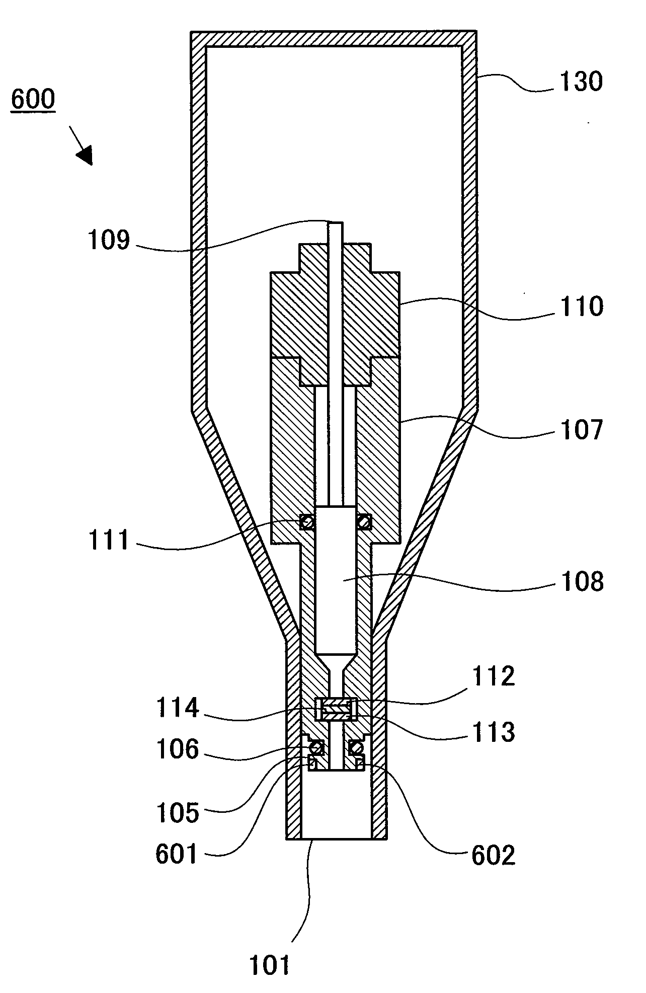
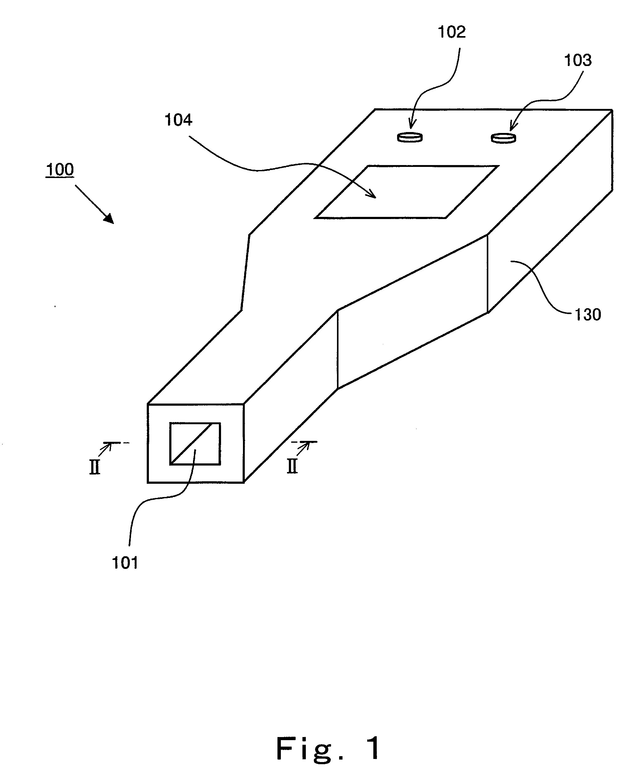
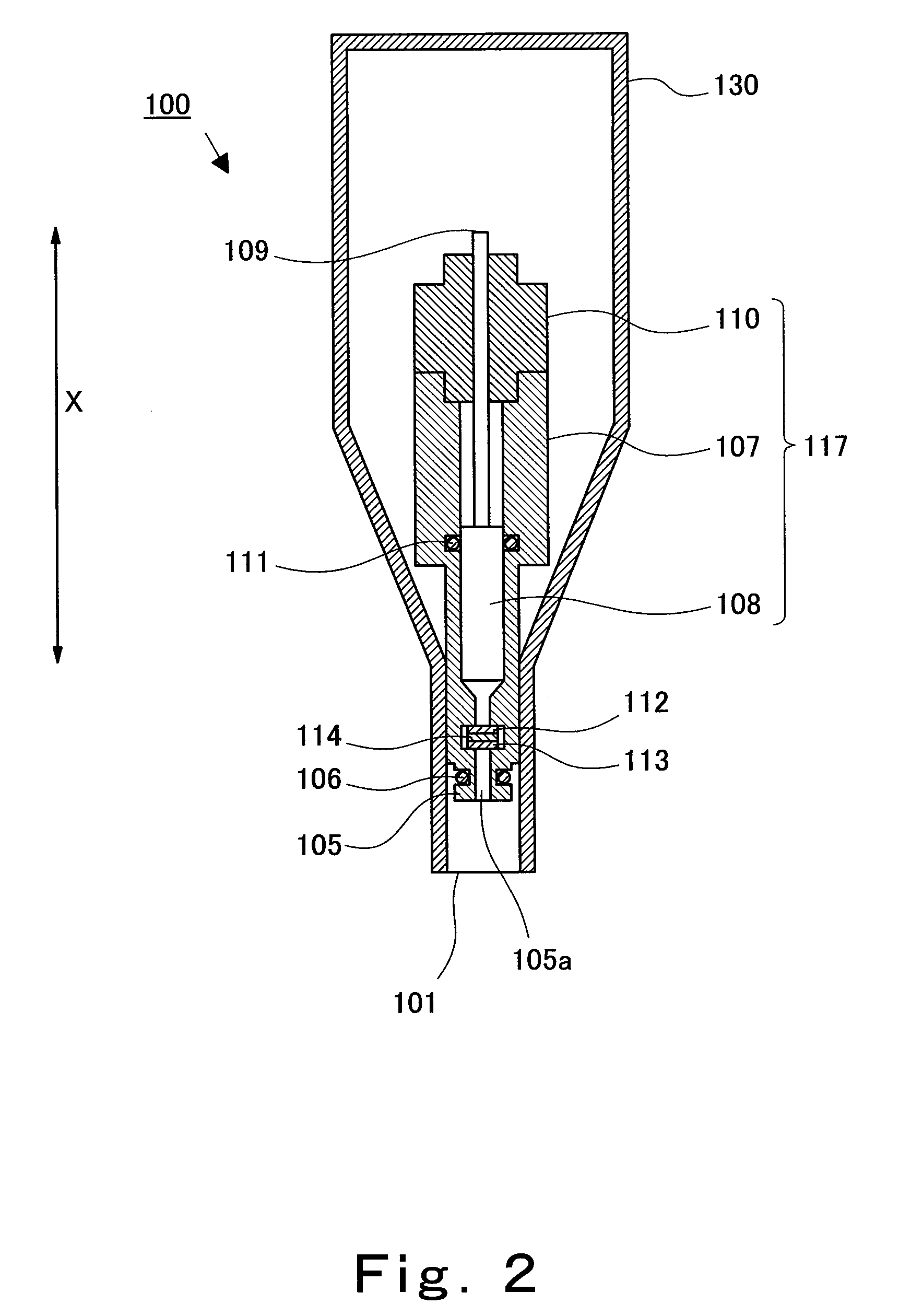
[0125]First, the configuration of a body fluid sampling device according to Embodiment 1 will be explained in reference to FIGS. 1 to 3.

[0126]FIG. 1 is a perspective view schematically showing the configuration of an appearance of the body fluid sampling device according to Embodiment 1 of the present invention. FIG. 2 is a cross-sectional view schematically showing the configuration of a cross section of the body fluid sampling device. FIG. 3 is a block diagram schematically showing an internal configuration of the body fluid sampling device.

[0127]As shown in FIG. 1, a body fluid sampling device 100 according to the present embodiment includes a casing 130. The casing 130 includes: a body fluid container attaching portion 101 to which a body fluid container is detachably attached; a body fluid suction start button 102 by which the supply of a body fluid to the body fluid container starts; a body fluid discharge button 103 by which the body fluid in the body fluid container is disch...

embodiment 2

[0183]Next, Embodiment 2 of the present invention will be explained in reference to FIGS. 15 and 16.

[0184]FIGS. 15 and 16 are diagrams showing the portion including the body fluid container and the vicinity of the connecting portion of the body fluid sampling device according to Embodiment 2 when the body fluid container is connected to the connecting portion.

[0185]Specifically, FIG. 15 is a longitudinal sectional view schematically showing the portion including the body fluid container and the vicinity of the connecting portion of the body fluid sampling device according to Embodiment 2 when the body fluid container is connected to the connecting portion. FIG. 16 is a cross-sectional view schematically showing the configuration of a cross section taken along line G-G′ of FIG. 15. In FIGS. 15 and 16, the casing is omitted for convenience sake.

[0186]The body fluid sampling device according to Embodiment 2 is different from the body fluid sampling device according to Embodiment 1 in t...

embodiment 3

[0193]Next, Embodiment 3 of the present invention will be explained in reference to FIGS. 19 and 20.

[0194]FIGS. 19 and 20 are diagrams showing the portion including the body fluid container and the vicinity of the connecting portion of the body fluid sampling device according to Embodiment 3 when the body fluid container is connected to the connecting portion.

[0195]Specifically, FIG. 19 is a longitudinal sectional view schematically showing the portion including the body fluid container and the vicinity of the connecting portion of the body fluid sampling device according to Embodiment 3 when the body fluid container is connected to the connecting portion. FIG. 20 is a cross-sectional view schematically showing the configuration of a cross section taken along line H-H′ of FIG. 19. In FIGS. 19 and 20, the casing is omitted for convenience sake.

[0196]The body fluid sampling device according to the present embodiment is different from the body fluid sampling device 100 according to Emb...


PUM

PropertyMeasurementUnit
voltageaaaaaaaaaa
depthaaaaaaaaaa
diameteraaaaaaaaaa

Abstract

A body fluid sampling device (100) includes: a connecting portion (105) to which a body fluid container is connected; a suctioning portion (117) which suctions a gas in the body fluid container connected to the connecting portion, to introduce a body fluid into the body fluid container; a suctioning passage (105a) which causes an inside of the suctioning portion and an inside of the body fluid container connected to the connecting portion, to be communicated with each other; a first electrode (112) which is disposed to extend across the suctioning passage and has gas permeability; a second electrode (113) which is disposed to extend across the suctioning passage and be opposed to the first electrode, and has gas permeability; and a detector which detects an electric signal generated between the first electrode and the second electrode. With this, the present invention provides the body fluid sampling device capable of detecting improper suctioning of the body fluid, and a body fluid measuring device using the body fluid sampling device.

Description

TECHNICAL FIELD[0001]The present invention relates to a body fluid sampling device which is used to obtain a body fluid, and a body fluid measuring device which uses the body fluid sampling device to measure the amount of a specific substance contained in the obtained body fluid.BACKGROUND ART[0002]A particular method for obtaining a certain amount of the body fluid is used to, for example, test, analyze, and quantitate the specific substance contained in the body fluid.[0003]One example of such method for obtaining a certain amount of the body fluid is pipetting using a pipetter. In the pipetting of the body fluid using the pipetter, an operation of obtaining the body fluid is comparatively easy. Therefore, the pipetting of the body fluid using the pipetter has been commonly used by many analysis engineers and the like. The pipetter is one type of liquid sampling device which accurately measures a certain amount of liquid when testing, analyzing, or quantitating a substance. Using ...

Claims


Application Information

Patent Timeline
Patent Type & Authority Applications(United States)
IPC IPC(8): A61B5/00G01N21/85
CPCA61B10/0045A61B10/007B01L3/0217B01L2200/0605G01N2035/1025B01L2300/0645G01N1/14G01N21/03G01N2021/0325B01L2200/14
Inventor NAKAMINAMI, TAKAHIRO
Owner PANASONIC CORP
Why Eureka
Try Eureka