Suction nozzle, and component mounting method and apparatus using the same

a technology of suction nozzle and component, which is applied in the direction of gripping heads, metal working apparatus, manufacturing tools, etc., can solve the problems of suction error and inconvenient deviation of suction nozzle from the component, and achieve the effect of increasing the allowance for positional deviation

Inactive Publication Date: 2006-06-08
HATA KANJI +3
View PDF4 Cites 12 Cited by
  • Summary
  • Abstract
  • Description
  • Claims
  • Application Information

AI Technical Summary

Benefits of technology

[0016] In the constructions described thus far, the sucking surface is formed so as to have a polygonal configuration including mutually-opposed sides parallel to the longitudinal direction of the component. This allows the suction nozzle to suck a component without interfering with the other components arranged in juxtaposition and to mount the component on a substrate without interfering with the already-mounted components. Thus, the suction nozzle is suited for a substrate having a high packaging density. Alternatively, the sucking surface may be formed so as to have a hexagonal configuration like a tortoiseshell pattern including mutually-opposed sides parallel to the longitudinal direction of a component. Further, even if the sucking surface is formed in the shape of an oval or an elongated ellipse, the corresponding effect is obtained.
[0017] Still further, by providing the nozzle opening with a narrowed portion whose opening diameter is made shorter than the dimension of the shorter side of the to-be-sucked surface of the component, it is possible to prevent the component from being sucked into the nozzle opening or being sucked in a stand-up or slanted state.
[0018] According to a third aspect of the invention, there is provided a component mounting method including the steps of: successively feeding components arranged in juxtaposition with their longer sides kept parallel to one another from a component supply portion to a predetermined position; sucking the components at the predetermined position by way of a suction nozzle designed so that a sucking surface for sucking a component by abutting on a to-be-sucked surface of the component is made larger in area than the to-be-sucked surface and is configured arbitrarily so long as a width in a major-axis direction of the component is smaller than a width in a minor-axis direction of the component; and mounting the sucked components on a substrate. In this method, the components arranged in juxtaposition with their longer sides kept parallel to one another are sucked by the suction nozzle having the sucking surface designed so that the width in a direction parallel to the longer side of the component is made smaller. This allows the suction nozzle to suck a component without interfering with the other components arranged in juxtaposition and to mount the component on a substrate without interfering with the already-mounted components.
[0019] According to a fourth aspect of the invention, there is provided a component mounting method including the steps of: successively driving a plurality of mounting heads with a suction nozzle, disposed around a rotary table which is intermittently rotated in one direction, to stop at a component supply position; successively driving, out of a multiplicity of component supply means arranged in juxtaposition on a component supply table which is moved in a direction tangent to a rotation circle of the rotary table, ones for supplying to-be-sucked components to stop at a predetermined position, so that a multiplicity of components arranged in juxtaposition are fed from the component supply means successively; suckingly holding, at the component supply position, the components fed from the component supply means by a suction nozzle, the component supply means being stopped at a predetermined position after selecting, either a first sucking position deviated upstream from a reference point, at which the rotation circle of the rotary table is tangent to a movement-direction line of the component supply table, along a rotation direction of the rotary table, or a second sucking position deviated downstream from the reference point along the rotation direction of the rotary table, the suction nozzle being so designed that a sucking surface for sucking a component by abutting on a to-be-sucked surface of the component is made larger in area than the to-be-sucked surface and is, configured arbitrarily so long as a width in a major-axis direction of the component at the first and second sucking positions, is smaller than a width in a minor-axis direction of the component; and mounting, when the mounting head is shifted to a component mounting position by an intermittent rotation, the component on a substrate. When a component is sucked at the position deviated upstream or downstream from the reference point, a positional deviation tends to occur between the component and the suction nozzle. However, with this method, since the sucking surface is made larger in area than the to-be-sucked surface of the component, it is possible to increase allowance for the positional deviation between the nozzle and components, thereby achieving the suction of components properly.
[0020] According to a fifth aspect of the invention, there is provided a component mounting apparatus including: a component supply portion for successively feeding components arranged in juxtaposition with their longer sides kept parallel to one another to a predetermined position; a suction nozzle designed so that a sucking surface for sucking a component by abutting on a to-be-sucked surface of the component is made larger in area than the to-be-sucked surface and is configured arbitrarily so long as a width in a major-axis direction of the component is smaller than a width in a minor-axis direction of the component; and a component mounting device for sucking the component at the predetermined position by way of the suction nozzle and for mounting the component on a substrate by moving the suction nozzle. In this construction, the components arranged in juxtaposition with their longer sides kept parallel to one another are sucked by the suction nozzle having the sucking surface designed so that the width in a direction parallel to the longer side of the component is made smaller. This allows the suction nozzle to suck a component without interfering with the other components arranged in juxtaposition and to mount the component on a substrate without interfering with the already-mounted components. Consequently, a component mounting apparatus is provided that suffers less from a suction error and is thus applicable to high-density mounting.
[0021] According to a sixth aspect of the invention, there is provided a component mounting method including the steps of: successively driving a plurality of mounting heads with a suction nozzle, disposed around a rotary table which is intermittently rotated in one direction, to stop at a component supply position; successively driving, out of a multiplicity of component supply means arranged in juxtaposition on a component supply table which is moved in a direction tangent to a rotation circle of the rotary table, ones for supplying to-be-sucked components to stop at a predetermined position, so that a multiplicity of components arranged in juxtaposition are fed from the component supply means successively; suckingly holding, at the component supply position, the components fed from the component supply means by a suction nozzle, the component supply means being stopped at a predetermined position after selecting, either a first sucking position deviated upstream from a reference point, at which the rotation circle of the rotary table is tangent to a movement-direction line of the component supply table, along a rotation direction of the rotary table, or a second sucking position deviated downstream from the reference point along the rotation direction of the rotary table, the suction nozzle being so designed that a sucking surface for sucking a component by abutting on a to-be-sucked surface of the component is made larger in area than the to-be-sucked surface and is configured arbitrarily so long as a width in a major-axis direction of the component to be sucked at the first and second sucking positions is smaller than a width in a minor-axis direction of the component; and mounting, when the mounting head is shifted to a component mounting position by an intermittent rotation, the component on a substrate. When a component is sucked at the position deviated upstream or downstream from the reference point along the rotation direction of the rotary table, a positional deviation tends to occur between the component and the suction nozzle. However, with this method, since the sucking surface is made larger in area than the to-be-sucked surface of the component, it is possible to increase allowance for the positional deviation between the nozzle and components, thereby achieving proper sucking operation. Consequently, a component mounting apparatus is provided that suffers less from a suction error and is thus applicable to high-density mounting.

Problems solved by technology

When the suction nozzle sucks a component, with a shaft of its sucking surface rotated at a certain angle with respect to the component, if the component has a fine size, the suction nozzle is inconveniently deviated from the component.
This leads to a suction error.

Method used


Image

  • Suction nozzle, and component mounting method and apparatus using the same
  • Suction nozzle, and component mounting method and apparatus using the same
  • Suction nozzle, and component mounting method and apparatus using the same

Examples


Embodiment Construction

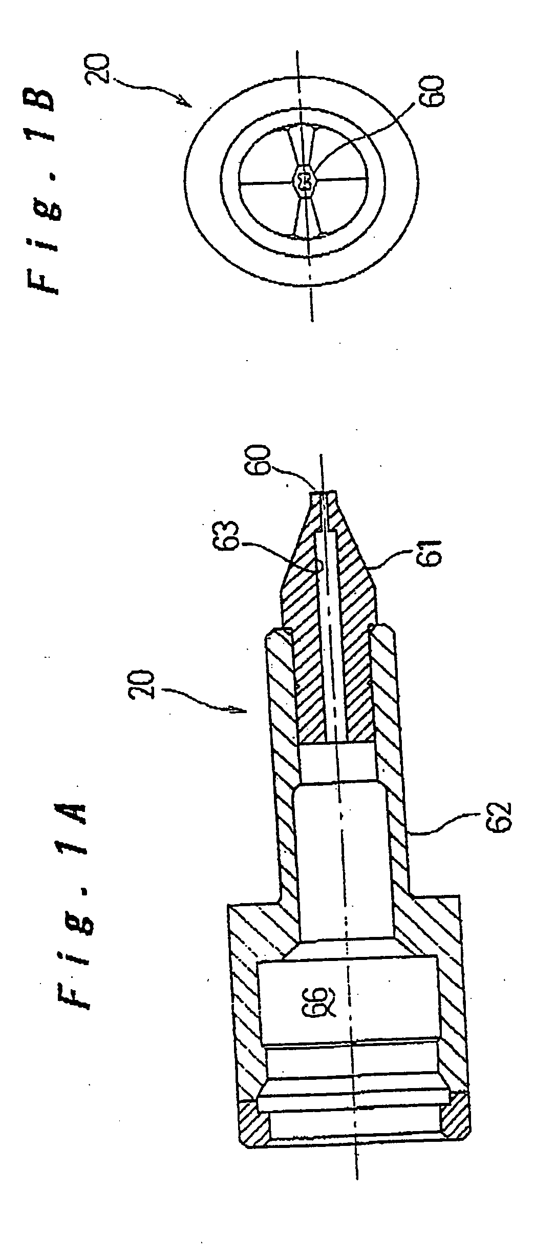
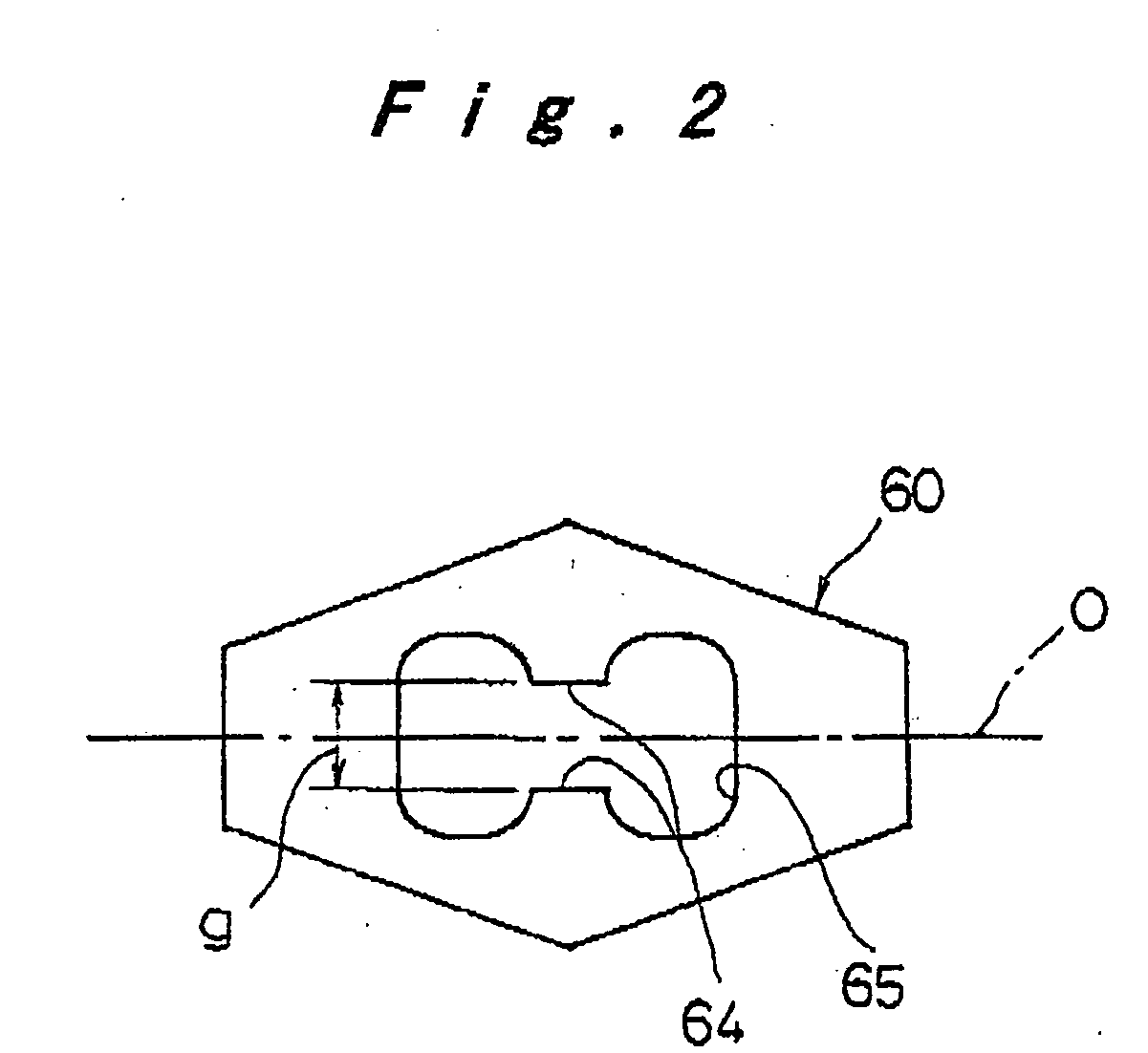
[0037] Hereinafter, an embodiment of the present invention will be described with reference to the accompanying drawings. It should be noted that the embodiment herein shown and described is to be taken merely one example of how the present invention is embodied, and thus the invention should not be limited thereto and various changes and modifications may be made without departing from the spirit and scope of the appended claims of the present invention.

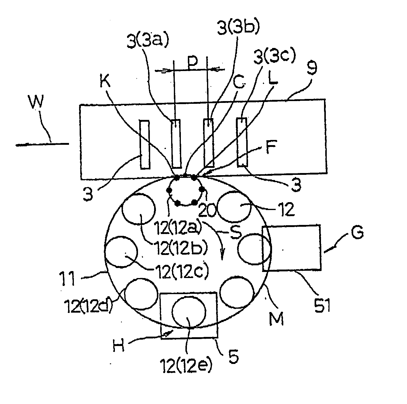
[0038] First, a description will be given as to the structure and operation of a component mounting apparatus to which a suction nozzle of the embodiment is applied. The structure and operation of this component mounting apparatus is proposed in Japanese Patent Application No. Hei. 10-303562 by the inventors of the present application. The entire structure of the component mounting apparatus is shown in FIGS. 13 and 14. As has already been explained in the description of the conventional art, the component mounting apparatus is con...


PUM

PropertyMeasurementUnit
sizeaaaaaaaaaa
sizeaaaaaaaaaa
areaaaaaaaaaaa

Abstract

In a suction nozzle (20), a sucking surface (60) is made larger in area than a to-be-sucked surface of a component (55) and is configured arbitrarily so long as a width (G1) between mutually-opposed sides parallel to a longer side (110) of the component to be sucked is smaller than a width (G2) in a direction parallel to a shorter side (111) of the component to be sucked. The suction nozzle sucks a component at its sucking surface, with a longitudinal axis (O) of the sucking surface (60) kept inclined with respect to a direction (J) in which the component is supplied.

Description

TECHNICAL FIELD [0001] The present invention relates to a component mounting method and apparatus for mounting an electronic component on a substrate, and more particularly to a suction nozzle for use in this component mounting apparatus. BACKGROUND ART [0002] As an example of electronic component mounting apparatuses for mounting an electronic component on a circuit board, a rotary head type apparatus is known. An apparatus of this type is capable of performing mounting at high speed, and thus has been in wide use as main equipment for manufacturing an electronic circuit board. FIG. 13 shows a conventional electronic component mounting equipment, and FIG. 14 shows a structure of a principal portion of a rotary head type electronic component mounting apparatus. A mounting portion 1 is configured to pick up a component from any of component supply means 3 provided in a component supply portion 2, and mount the component on a substrate 5 set on an X-Y table 4. [0003] In the component ...

Claims


Application Information

Patent Timeline
Patent Type & Authority Applications(United States)
IPC IPC(8): A47J45/00H05K13/04
CPCH05K13/0408Y10T29/53178Y10T29/49131Y10T29/53191H05K13/0409
Inventor HATA, KANJIOJI, SHIROKOSAKA, KAZUAKIMORIMOTO, MASAHIRO
Owner HATA KANJI
Why Eureka
Try Eureka