Solar Cell Interconnection on a Flexible Substrate

a flexible substrate and solar cell technology, applied in the field of solar cell arrays, can solve the problems of high-power density solar modules to be used, and achieve the effect of high packing density

Inactive Publication Date: 2010-11-11
EMCORE SOLAR POWER
View PDF92 Cites 92 Cited by
  • Summary
  • Abstract
  • Description
  • Claims
  • Application Information

AI Technical Summary

Benefits of technology

[0009]It is an object of the present invention to provide a solar cell array on a film substrate with a high packing density, preferably not lower than 85%.

Problems solved by technology

A key issue in the development of thin-film solar cells for space applications has been the production of high-power density solar modules to be used as the primary power source for spacecraft.

Method used


Image

  • Solar Cell Interconnection on a Flexible Substrate
  • Solar Cell Interconnection on a Flexible Substrate
  • Solar Cell Interconnection on a Flexible Substrate

Examples


Embodiment Construction

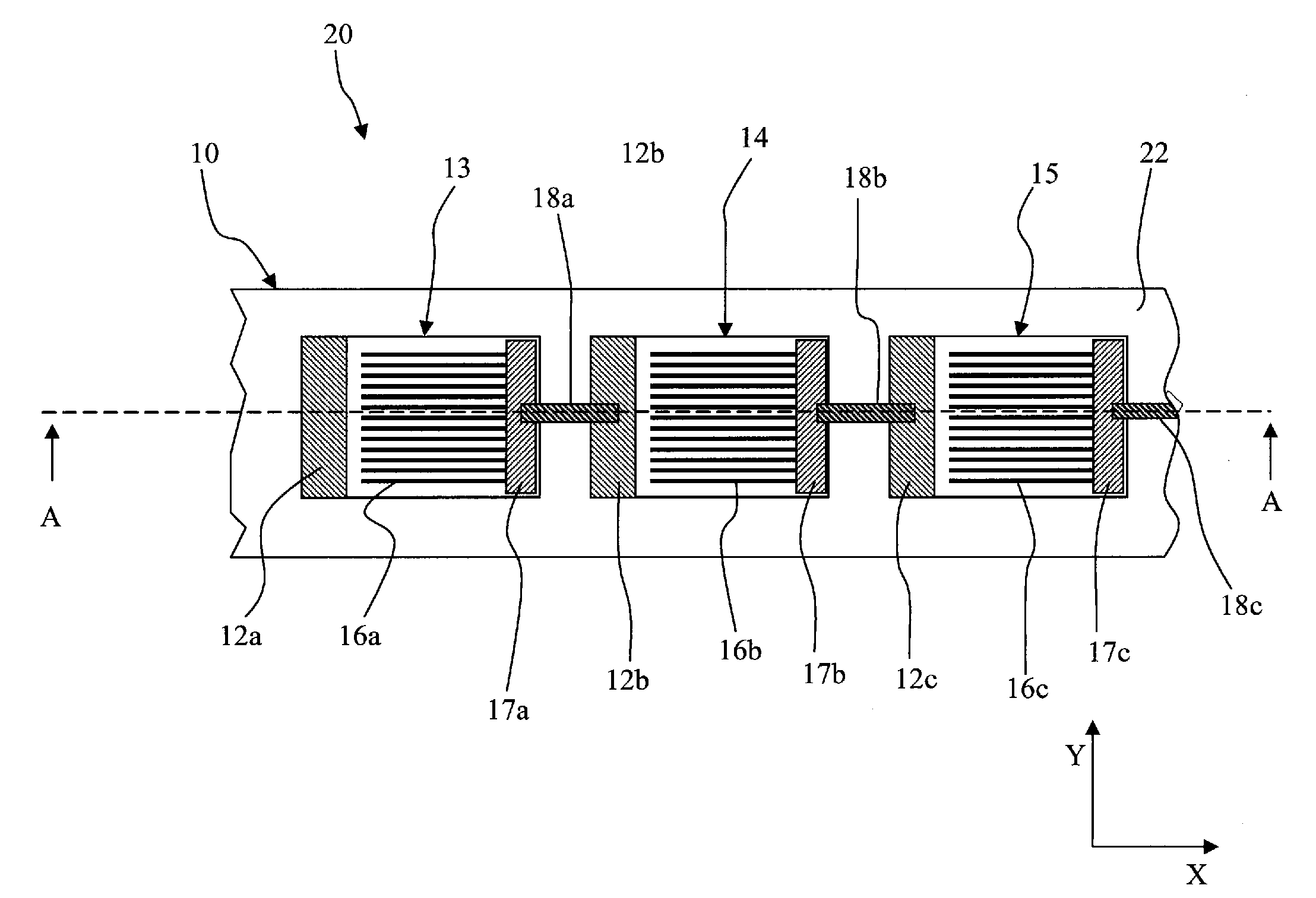
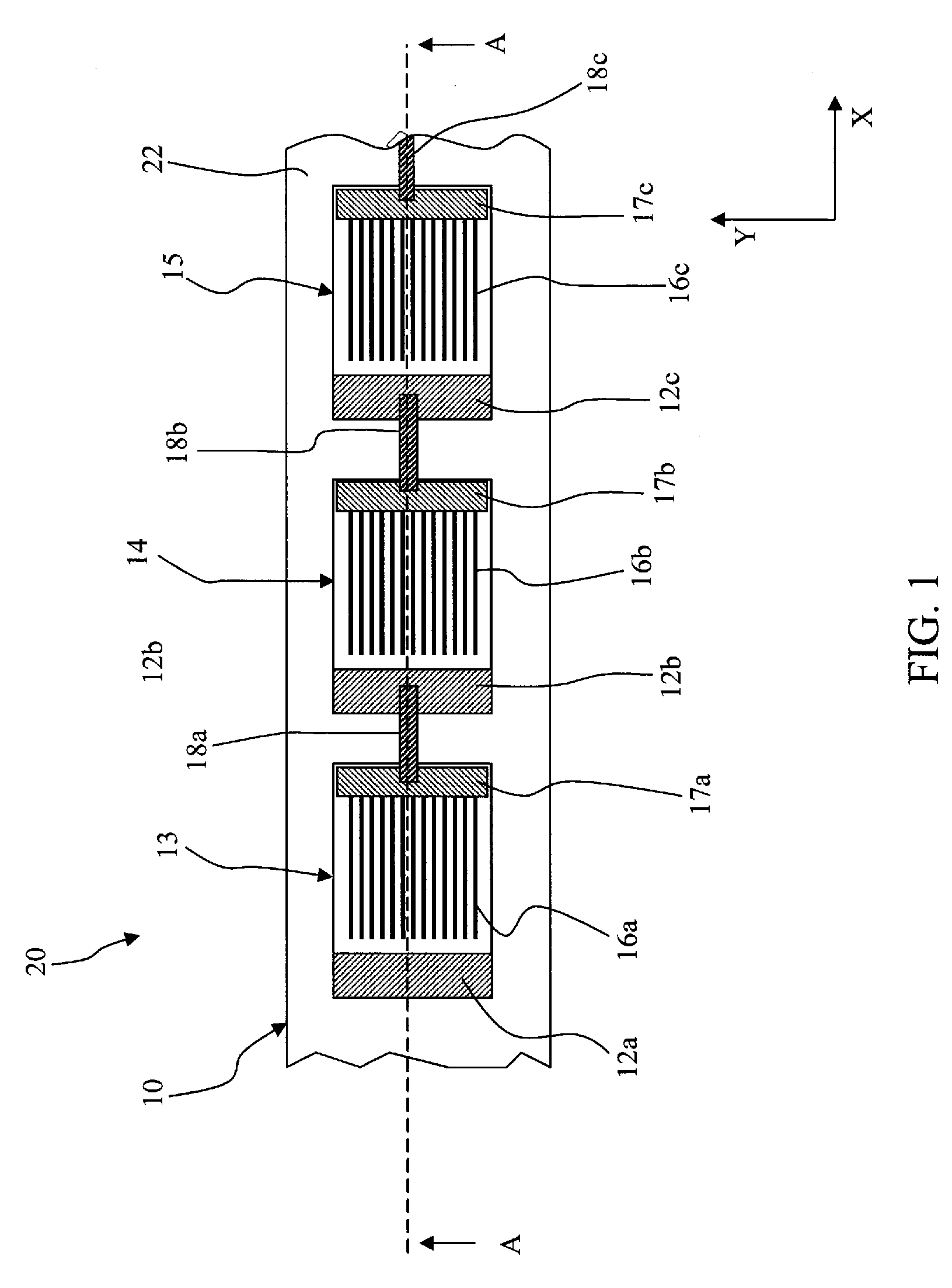
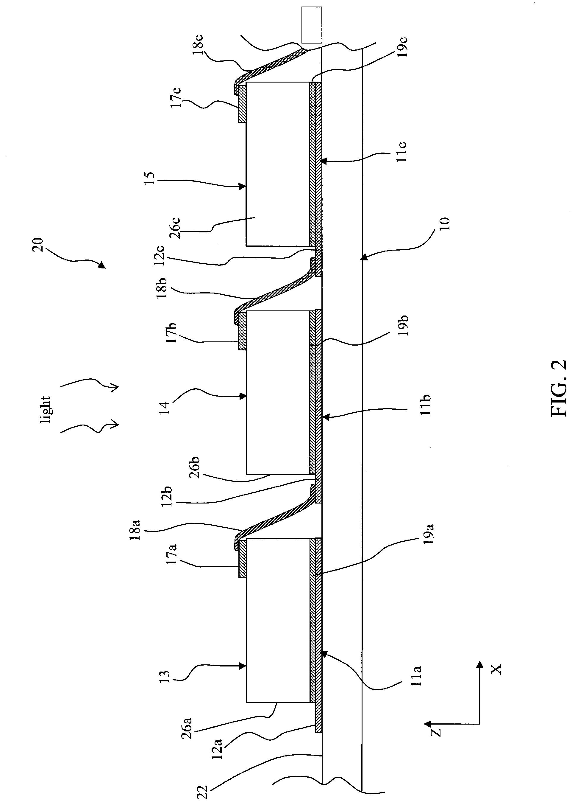
[0021]FIGS. 1 and 2 illustrates, respectively, a partial plan view and a cross-sectional view of a solar cell array arranged on a common flexible substrate and comprising a plurality of individual solar cells electrically interconnected. As used herein, the term “plurality” indicates “at least two”, and typically much larger than two (e.g., 50 to 100), where the number of individual cells in the array can widely vary depending on the application and on the output power required from the array. For simplicity, three individual solar cells 13, 14 and 15 of solar cell array 20 are illustrated in FIGS. 1 and 2. The cross-sectional view illustrated in FIG. 2 is taken along line A-A of FIG. 1 of the longitudinal “X” direction indicated in the figures and representing the main direction of arrangement of the solar cells in the array.

[0022]The solar cell array 20 can be part of a photovoltaic module, namely a packaged interconnected assembly of solar cells comprising one or more solar cell ...


PUM

PropertyMeasurementUnit
thicknessaaaaaaaaaa
lengthaaaaaaaaaa
lengthaaaaaaaaaa

Abstract

A solar cell array comprising: a substrate having a carrier surface on which a plurality of electrically conductive bonding pads are provided, the bonding pads being spaced from one another along a main direction; a plurality of solar cells, each solar cell of the plurality including a back electrode bonded to a first portion of a respective bonding pad, wherein each bonding pad comprises a second portion defining an exposed contact region not covered by the back electrode of the respective solar cell, and wherein an interconnecting lead electrically connects the second portion of the bonding pad associated with a first solar cell with an electrode of a directly adjacent second solar cell.
The substrate is an electrically insulating substrate and preferably a flexible film, made for instance of polyimide material.

Description

BACKGROUND OF THE INVENTION[0001]1. Field of the Invention[0002]The present invention relates to solar cell arrays of interconnected individual cells mounted on an electrically insulating substrate, and in particular to methods for assembling a high density solar cell arrays.[0003]2. Description of Related Art[0004]Solar cells are photovoltaic devices that convert sunlight directly into electrical power.[0005]Thin-film technology has gained widespread interest in satellite and in general space applications because of their low cost, high-density packaging, and radiation resistance. Thin-film solar cells can be in general based on different semiconductors materials, such as polycrystalline or amorphous silicon, binary to quaternary alloys of III-V semiconductors, CdTe- or copper-indium-gallium selenide (CIGS) based materials. A key issue in the development of thin-film solar cells for space applications has been the production of high-power density solar modules to be used as the pri...

Claims


Application Information

Patent Timeline
Patent Type & Authority Applications(United States)
IPC IPC(8): H01L31/042B32B37/12B32B37/02
CPCH01L31/02008H01L31/0508Y02E10/50
Inventor CORNFELD, ARTHUR
Owner EMCORE SOLAR POWER
Why Eureka
Try Eureka