High-Fiber-Density Optical Fiber Cable

a fiber optic cable, high-density technology, applied in the direction of optics, fibre mechanical structures, instruments, etc., can solve the problems of signal attenuation, and unsatisfactory mid-span storage performance of constituent buffer tubes positioned in pedestals, cabinets, or other optical fiber enclosures, and achieve high cable fiber densities and improve attenuation performan

Active Publication Date: 2010-03-18
DRAKA COMTEQ BV
View PDF22 Cites 95 Cited by
  • Summary
  • Abstract
  • Description
  • Claims
  • Application Information

AI Technical Summary

Benefits of technology

[0009]Accordingly, it is an object of the present invention to provide optical-fiber cables possessing high cable fiber densities while ensuring that the

Problems solved by technology

Packing fibers into tight spaces can cause undesirable attenuation.
Such optical-fiber cables can achieve higher fiber densities, but the constituent buffer tubes have un

Method used


Image

  • High-Fiber-Density Optical Fiber Cable
  • High-Fiber-Density Optical Fiber Cable

Examples


example

[0107]Table 1 (below) compares a comparative optical-fiber cable to an exemplary optical-fiber cable of the present invention.

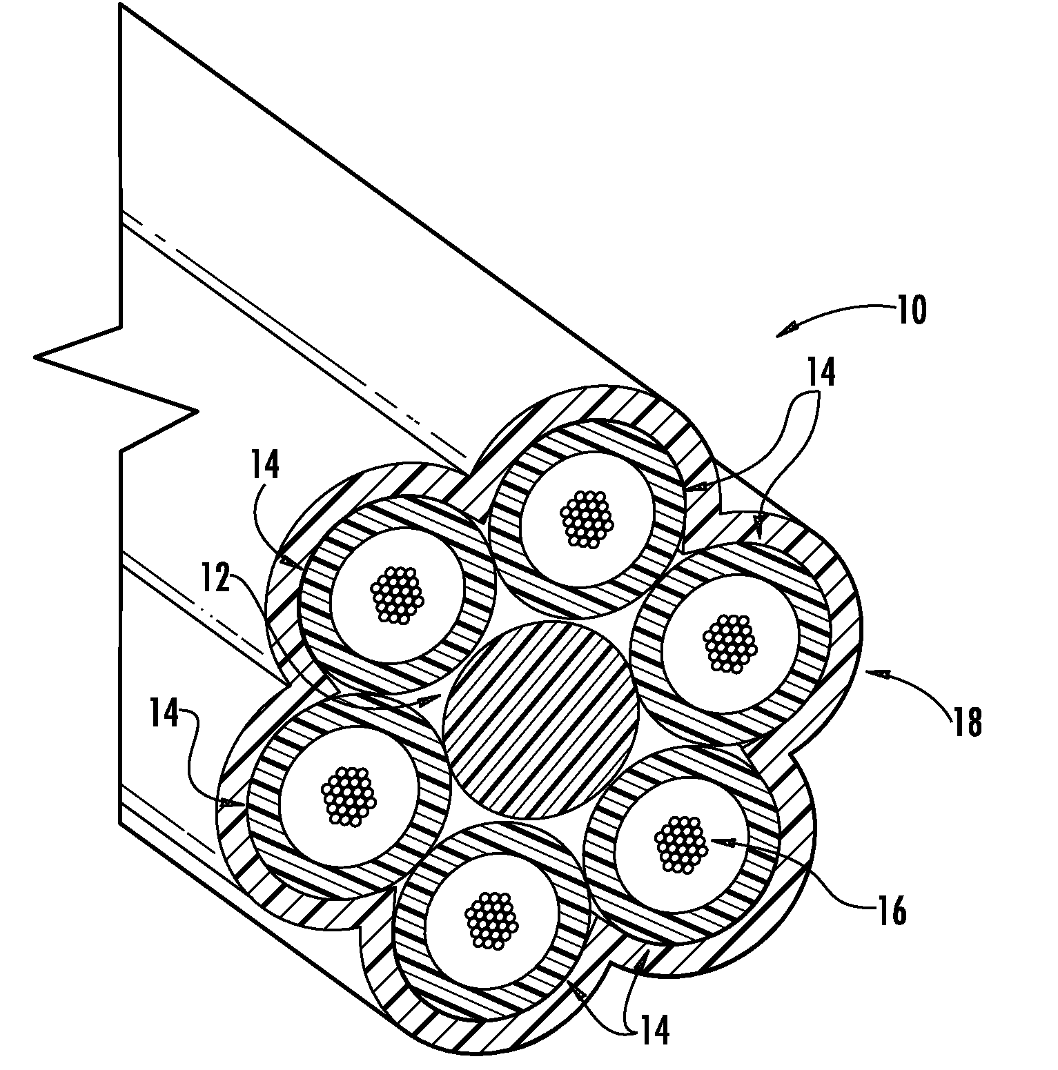
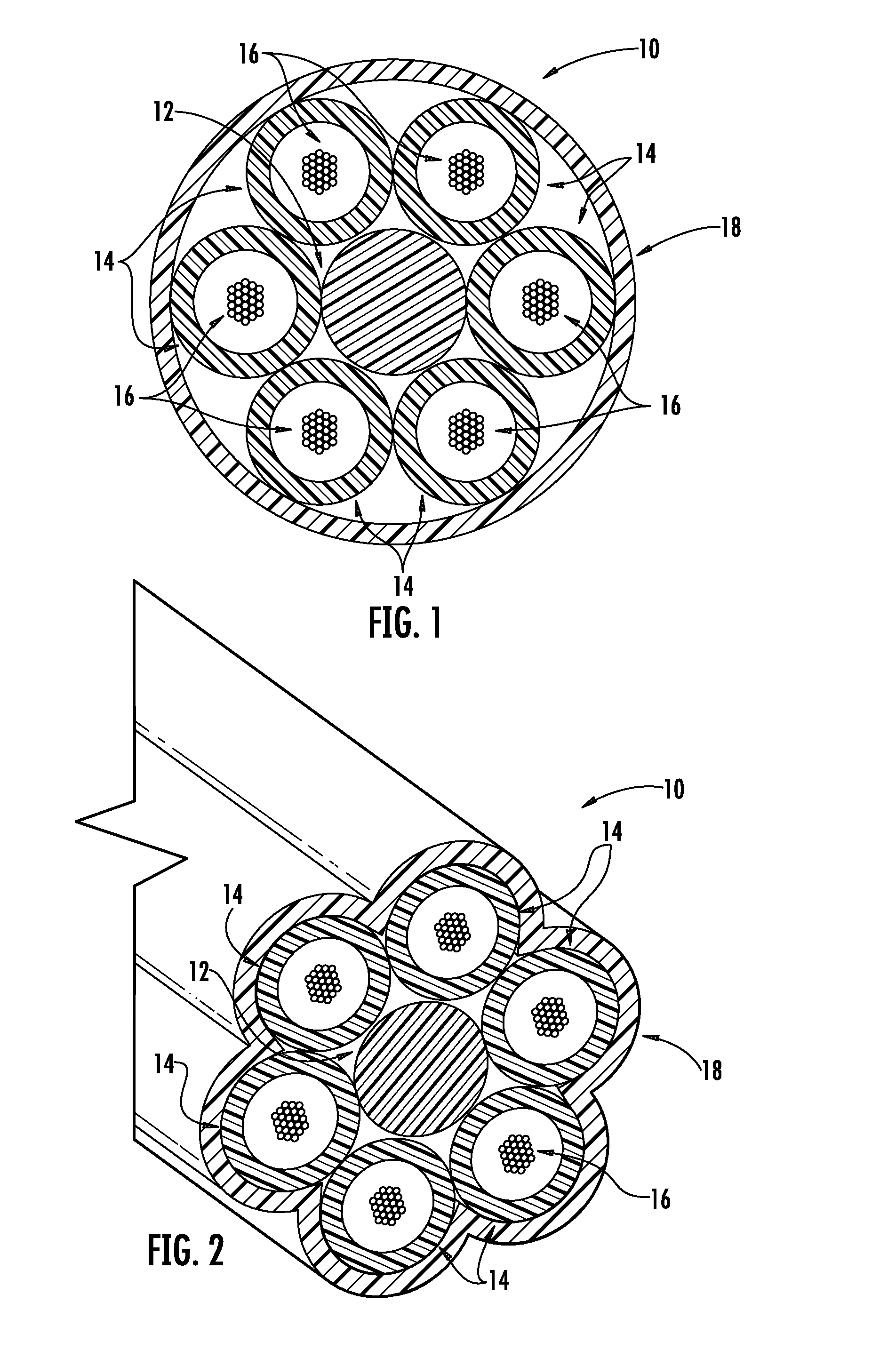
TABLE 1InventiveComparativeCableCablecable configurationbuffer tubes per cable612fibers per buffer tube2412optical-fibers per cable144144optical-fiber informationoptical-fiber diameter (μm)242242optical-fiber area (μm2)45,99645,996total optical-fiber area (mm2)6.6236.623buffer-tube informationtube outer diameter (mm)31.9tube inner diameter (mm)2.21.2buffer-tube area (mm2)3.8011.131total buffer-tube area (mm2)22.80813.572cable informationcable outer diameter (mm)10.511.1cable outer area (mm2)86.59096.769cable inner diameter (mm)9.39.9cable inner area (mm2)67.92976.977cable propertiescable filling coefficient (inner)0.0980.086outer cable filling coefficient0.0760.068cable fiber density (fibers / mm2)1.6631.488cumulative buffer tube0.2900.488filling coefficient

[0108]Both optical-fiber cables depicted in Table 1 contain 144 optical fibers and were designed to be in...


PUM


Abstract

Disclosed is a fiber-optic cable that possesses a high cable filling coefficient (and/or a high cable fiber density) yet ensures that its enclosed optical fibers demonstrate improved attenuation performance when subjected to temperature variations between about −40° C. and 70° C. The fiber-optic cable is suitable for efficient installation into ducts, such as via blowing.

Description

CROSS-REFERENCE TO PRIORITY APPLICATIONS[0001]This application claims the benefit of U.S. Patent Application No. 61 / 096,750 for a “High-Fiber-Density Optical Fiber Cable” (filed Sep. 12, 2008), and U.S. Patent Application No. 61 / 113,146 for a “High-Fiber-Density Optical Fiber Cable” (filed Nov. 10, 2008), each of which is incorporated by reference in its entirety.FIELD OF INVENTION[0002]The present invention relates to optical-fiber cables and, more generally, to electrical or other communication signal carriers. The present invention, for instance, embraces an optical-fiber cable design that is particularly suitable for blown installation into microducts.BACKGROUND OF THE INVENTION[0003]As compared with traditional wire-based networks, optical-fiber communication networks are capable of transmitting significantly more information at significantly higher speeds. Optical fibers, therefore, are being increasingly employed for communication networks.[0004]To expand total transmission t...

Claims


Application Information

Patent Timeline
IPC IPC(8): G02B6/44
CPCG02B6/4411G02B6/4464G02B6/4438G02B6/52
Inventor LOVIE, RAYBARKER, JEFFREY SCOTTSMARTT, WILLIAM MARKOVERTON, BOB J.
Owner DRAKA COMTEQ BV
Why Eureka
Try Eureka