Internal combustion engine silencer

a technology of internal combustion engine and silencer, which is applied in the direction of engines, machines/engines, mechanical equipment, etc., to achieve the effect of greater attenuation

Inactive Publication Date: 2005-10-13
SANGO CO LTD
View PDF11 Cites 25 Cited by
  • Summary
  • Abstract
  • Description
  • Claims
  • Application Information

AI Technical Summary

Benefits of technology

[0018] With this configuration, an even greater attenuating effect can be achieved without reducing the attenuating effect in the high revolution range of the engine by boring the interference holes in the inlet pipe.

Problems solved by technology

With this configuration, exhaust noise flowing in the expanding chamber in one direction flows into the outlet pipe through the interference holes bored in the outlet pipe, interferes with exhaust noise flowing in the outlet pipe in the direction reverse to the flowing direction in the expanding chamber, and is attenuated by that interfering action.

Method used


Image

  • Internal combustion engine silencer
  • Internal combustion engine silencer
  • Internal combustion engine silencer

Examples


first embodiment

[0031]FIG. 1 and FIG. 4 show the invention.

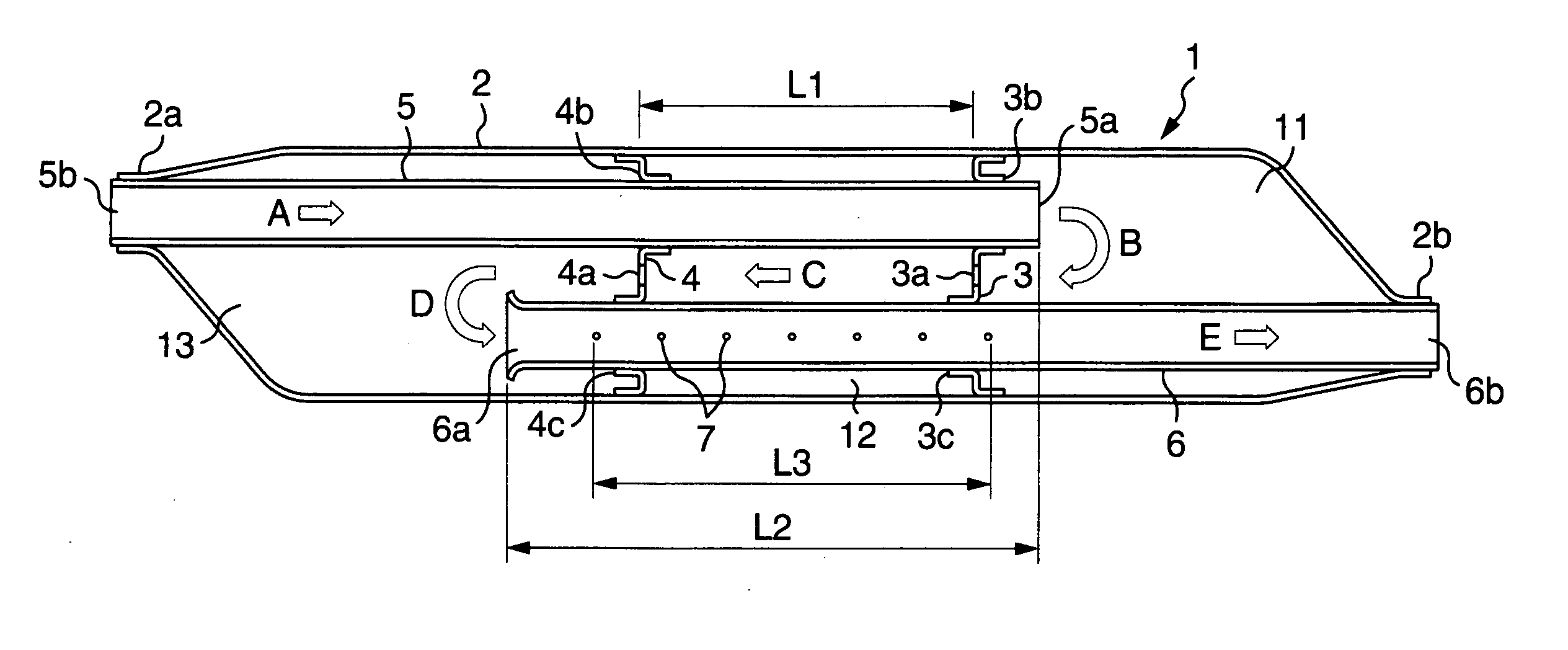
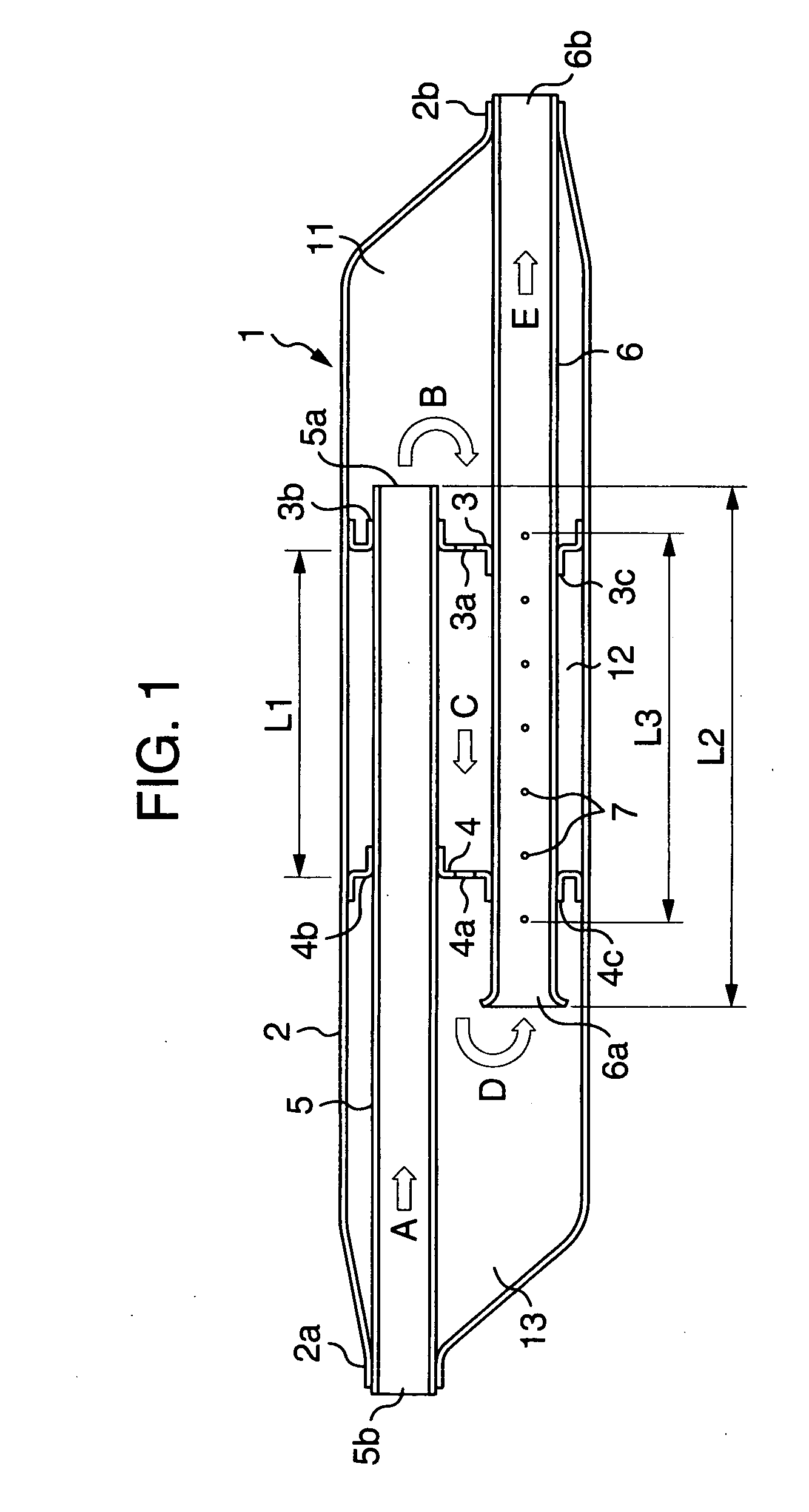
[0032] In FIG. 1, a housing 2 in a muffler 1 is constituted of a metallic cylinder of which both ends are reduced in diameter to form constrictions 2a and 2b.

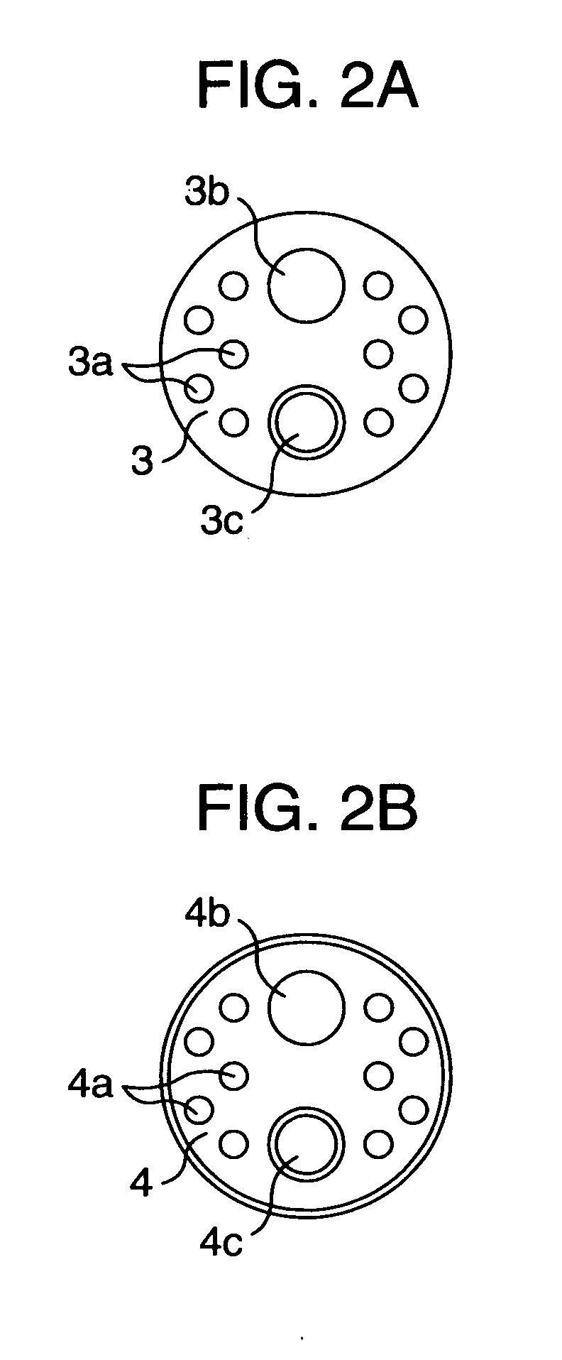
[0033] In the housing 2, a separator 3 in which a plurality of through holes 3a and two burring holes 3b and 3c are bored as shown in FIG. 2A and a separator 4 in which a plurality of through holes 4a and two burring holes 4b and 4c are bored as shown in FIG. 2B are fixed with a prescribed spacing L1 between them, and they partition the housing 2 in the lengthwise direction into a first expanding chamber 11, a second expanding chamber 12 and a third expanding chamber 13.

[0034] In the housing 2, forcing into its constriction 2a and the burring holes 3b and 4b of the separators 3 and 4, an inlet pipe 5 for introducing exhaust gas into the muffler 1 is disposed, and its downstream side aperture 5a opens into the first expanding chamber 11. Incidentally, an upstream side aperture 5b is c...

second embodiment

[0047]FIG. 5 and FIG. 6 show the invention.

[0048] Referring to FIG. 5, the housing of a muffler 21 is composed of a shell 22 cylindrically formed of a steel plate and outer plates 23 and 24 caulk-coupled to both ends of the shell 22. Within the housing, a separator 31 in which a plurality of through holes 31a and a burring hole 31b are bored as shown in FIG. 6 is fixed, and the housing is partitioned by the separator 31 into a first expanding chamber 29 and a second expanding chamber 30.

[0049] An inlet pipe 25, positioned on the first expanding chamber 29 side, is inserted into a burring hole 22a of the shell 22, with its end being blocked by a cap 27 disposed in the opposite position to the burring hole 22a.

[0050] Further, in the side face of the inlet pipe 25 are bored discharge ports (apertures) 28 so that exhaust gas in the inlet pipe 25 can flow into the first expanding chamber 29 via the discharge ports 28.

[0051] An outlet pipe 26 is inserted into a burring hole 24a of an o...

third embodiment

[0058]FIG. 7 shows the invention.

[0059] Referring to FIG. 7, the housing 42 of a muffler 41 is constituted of a metallic cylinder of which both ends are coaxially reduced in diameter to form a constriction 42a and a constriction 42b.

[0060] In the housing 42, the separator 3 in which through holes 3a are bored as shown in the first embodiment and the separator 4 in which the through holes 4a are bored are fixed with the prescribed spacing L1 between them, and they partition the housing 42 in the longitudinal direction into a first expanding chamber 51, a second expanding chamber 52 and a third expanding chamber 53.

[0061] In the housing 42, as in the foregoing embodiment, an inlet pipe 45 for introducing exhaust gas into the muffler 41 is disposed, held by the constriction 42a and the separators 3 and 4, and an aperture 45a on its downstream side opens into the first expanding chamber 51. Incidentally, an aperture 45b on its upstream side is connected to an upstream exhaust pipe.

[0...


PUM


Abstract

A muffler for internal combustion engines, in order to achieve a high attenuating effect without reducing the attenuating effect in the high revolution range of the engine, comprising one or more expanding chambers 11 through 13 formed in a muffler 1, an inlet pipe 5 which opens into a expanding chamber 11 and introduces exhaust gas into the muffler 1, and an outlet pipe 6 which opens into other expanding chamber 13 and introduces exhaust gas out of the muffler 1. In the muffler, the exhaust gas discharged through an aperture 5a of this inlet pipe 5 is inverted once or more times in the muffler 1 and is introduced into an aperture 6a of the outlet pipe 6. In a contraflow area L2 in which the flowing direction C of exhaust gas flowing in the expanding chambers 11 through 13 and the flowing direction E of exhaust gas flowing in the outlet pipe 6 are not the same, interference holes 7 composing of a plurality of small holes communicating with the expanding chambers 11 through 13 are bored in the outlet pipe 6. The aperture area of the small holes 7 is kept at not less than 1% but not more than 5% of the surface area of the outlet pipe in the contraflow area L2.

Description

TECHNICAL FIELD [0001] The present invention relates to an international combustion engine silencer, or a muffler for internal combustion engines. BACKGROUND ART [0002] Among mufflers to be disposed on the exhaust line of an internal combustion engine are conventionally known ones having a U-turn structure in which exhaust gas is inverted once or more in the muffler. As a muffler having such a U-turn structure, the muffler illustrated in FIG. 11, for instance, is disclosed in the Japanese Utility Model Unexamined Publication JP-U-61-194718. [0003] The muffler, as shown in FIG. 11, is provided within its housing 101, successively from the upstream side (left side in the drawing) onward, a first expanding chamber 102, a second expanding chamber 103, a third expanding chamber 104 and a resonator chamber 105 partitioned from one another. In the third expanding chamber 104 opens an inlet pipe 106 for introducing exhaust gas into the muffler, and the first expanding chamber 102 is provide...

Claims


Application Information

Patent Timeline
Patent Type & Authority Applications(United States)
IPC IPC(8): F01N1/00F01N1/06F01N1/08
CPCF01N1/06F01N1/084F01N1/089F01N1/10F01N3/00F01N13/1872F01N13/1888F01N2260/10F01N2470/02F01N2470/04F01N2470/10F01N2470/18F01N2470/20
Inventor YOKOI, MASAYUKIMIZUNO, FUMIHIKO
Owner SANGO CO LTD
Why Eureka
Try Eureka