New LED back light module

A backlight module and light scattering technology, applied in optics, optical components, nonlinear optics, etc., can solve problems that hinder the popularization and application of LED backlight technology, and achieve the effects of improving competitiveness, high degree of design freedom, and simple manufacturing process

Active Publication Date: 2007-10-03
BOE TECH GRP CO LTD
View PDF0 Cites 24 Cited by
  • Summary
  • Abstract
  • Description
  • Claims
  • Application Information

AI Technical Summary

Problems solved by technology

All the above-mentioned shortcomings have hindered the popularizati

Method used


Image

  • New LED back light module
  • New LED back light module
  • New LED back light module

Examples


Embodiment 1

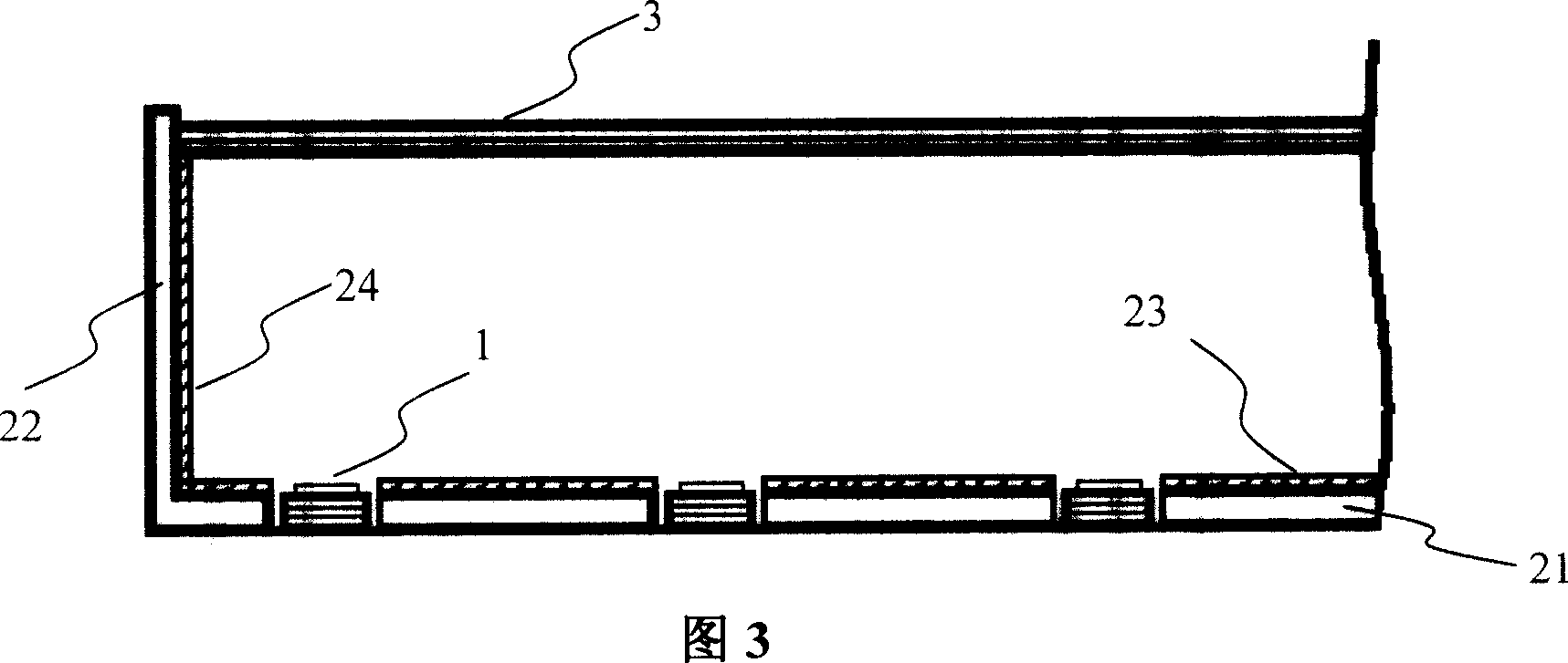
[0027] Embodiment 1: FIG. 4 shows an embodiment of an LED backlight module provided by the present invention. There are housing, LED array 1, a conical semi-reflective half-lens array 41, light scattering and refracting mechanism 3 composed of several diffusion films (plates) and prism films.

[0028] A small hole array corresponding to the LED array 1 is dug in the bottom 21 of the housing, and the LED array 1 is installed in the small hole array, and the light scattering and refracting mechanism 3 is installed on the top of the module, and its upper surface is the light emitting surface of the module. The material of the shell may be metal materials such as aluminum alloy or the like. The LED used is a high-brightness top-emitting white LED. The white light emission mechanism of the LED can be emitted by the excited phosphor powder, or it can be mixed into white light by R\G\B.

[0029] The housing bottom 21 inner wall except the small hole and the housing side wall are pas...

Embodiment 2

[0031] Embodiment two: as shown in Figure 5, improve on the basis of specific embodiment one, add a diffusion film (plate) 5 again between LED array 1 and the tapered half-mirror array, wherein the diffusion film The (plate) 5 may also be a prism film or other optical films and combinations thereof.

Embodiment 3

[0032] Embodiment 3: As shown in FIG. 6 , the difference from Embodiment 1 is that the optical structural unit with partial reflection and partial transmission functions is a Fresnel lens 43 . Fresnel lenses can be easily produced by injection molding using known knowledge.


PUM


Abstract

The new LED back light module includes LED units on a base plate, one casing and one light scattering and refracting mechanism with outer vertical plane as the outgoing plane. It features the partially reflecting and partially transmitting optical structure unit set in the light outgoing direction of the LED units and with structure independently to the LED units. The light from the LED' s is transmitted partially and scattered mostly in the optical structure unit so as to avoid LED shade spot in the light outgoing plane of the module. The optical structure unit may be regulated flexibly to reach proper ratio between the transmitted light and the scattered light. The present invention is suitable for various kinds of LED light source.

Description

technical field [0001] The present invention relates to an LED (Light Emitting Diode) backlight module, in particular to an LED backlight module with an array composed of optical structural units with partial reflection and partial transmission functions. Background technique [0002] Currently, liquid crystal displays (LCDs) have become the mainstream in the field of flat panel displays. Since liquid crystal itself does not emit light, LCD needs to realize transmissive or reflective display through an external light source. Most of the existing LCDs are transmissive, and for these transmissive LCDs, the backlight source is an indispensable component. [0003] Compared with the traditional cold cathode lamp (CCFL), the backlight module using LED as the light source has the advantages of good color reproduction, power saving, good environmental adaptability, and less pollution. LCD with LED backlight can show more vivid colors, and its color reproduction range can reach mor...

Claims


Application Information

Patent Timeline
IPC IPC(8): G02F1/13357G02F1/1335H01L33/00G02B3/08H01L33/58
Inventor 刘敬伟王刚李俊峰任建昌王大巍孙润光
Owner BOE TECH GRP CO LTD
Why Eureka
Try Eureka