Piezoelectric active vibration isolating mechanism and method for reducing inherent frequency of vibrating system

An active vibration isolation and vibration system technology, which is applied in control/regulation systems, non-rotational vibration suppression, non-electric variable control, etc., can solve the problems of attenuating low-frequency interference, high rigidity of piezoelectric ceramics, and high natural frequency of structures

Active Publication Date: 2015-12-09
HUAZHONG UNIV OF SCI & TECH
View PDF5 Cites 24 Cited by
  • Summary
  • Abstract
  • Description
  • Claims
  • Application Information

AI Technical Summary

Problems solved by technology

However, the high rigidity of piezoelectric ceramics leads to high natural frequencies of the structure, making it difficult to effectively attenuate low-frequency interference. Therefore, a d

Method used


Image

  • Piezoelectric active vibration isolating mechanism and method for reducing inherent frequency of vibrating system
  • Piezoelectric active vibration isolating mechanism and method for reducing inherent frequency of vibrating system
  • Piezoelectric active vibration isolating mechanism and method for reducing inherent frequency of vibrating system

Examples


Embodiment 1

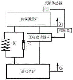
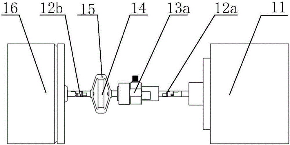
[0037] Referring to Figure 1(a), figure 2 And Fig. 3 (a), a kind of piezoelectric active vibration isolation mechanism, comprises first flexible hinge 12b, piezoelectric actuator, force sensor 13a, second flexible hinge 12a and controller, one end of described first flexible hinge 12b For connecting the base platform 16, the other end of which is sequentially connected to the piezoelectric actuator, the force sensor 13a and the second flexible hinge 12a, and the other end of the second flexible hinge 12a is used to connect to the load platform 11;

[0038] Both the piezoelectric actuator and the force sensor 13a are connected to the controller;

[0039] The force sensor 13a is used to detect the vibration signal of the load platform 11, and transmit the vibration signal to the controller, and the controller adopts the PI feedback control method to control the piezoelectric actuator to apply force on the load platform 11, thereby exerting force on the load platform 11. perform...

Embodiment 2

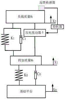
[0057] A piezoelectric active vibration isolation mechanism, including a first force sensor 23b, a spring bellows 27, an intermediate mass 26, a first flexible hinge 22b, a piezoelectric actuator, a second force sensor 23a, a second flexible hinge 22a and a control device, among them,

[0058] One end of the first force sensor 23b is used to connect to the base platform 28, and the other end is sequentially connected to the second force sensor 23b, the spring bellows 27, the intermediate mass 26, the first flexible hinge 22b, the piezoelectric actuator, A second force sensor 23a, a second flexible hinge 22a, the other end of the second flexible hinge 22a is used to connect to the load platform 21;

[0059] The first force sensor 23b, the piezoelectric actuator and the second force sensor 23a are all connected to the controller;

[0060] The first pressure sensor 23b and the second pressure sensor 23a are used to detect the vibration signals of the base platform 28 and the loa...


PUM


Abstract

The invention discloses a piezoelectric active vibration isolating mechanism which comprises a first force sensor, a spring corrugated pipe, an intermediate mass block, a first flexible hinge, a piezoelectric actuator, a second force sensor, a second flexible hinge and a controller. One end of the first force sensor is connected with a base platform, and the other end of the first force sensor is sequentially connected with the second force sensor, the spring corrugated pipe, the intermediate mass block, the second flexible hinge, the piezoelectric actuator and the first flexible hinge. The first force sensor and the second force sensor are respectively used for detecting the vibrating signals of the base platform and the vibrating signals of a load platform and can respectively transmit the detecting vibrating signals to the controller, and the controller can control the piezoelectric actuator to exert acting force on the load platform to compensate the load platform. By means of a two-stage serial-connection suspending structure, the inherent frequency of the structure is effectively reduced, and micro-vibration low-frequency interference in precision equipment can be effectively restrained.

Description

technical field [0001] The invention belongs to the field of micro-vibration suppression, and more specifically relates to a piezoelectric active vibration isolation mechanism and a method for reducing the natural frequency of a vibration system. Background technique [0002] Traditional passive vibration isolators are composed of mass-spring-damping elements. Due to the inherent contradiction between the transmission rate of low-frequency vibration and the attenuation rate of high-frequency vibration, they cannot meet the vibration isolation requirements of precise micro-vibration. Therefore, some New technologies, new methods to improve this situation. For example, during the satellite’s in-orbit operation, the normal operation of the equipped equipment will cause the overall and local reciprocating motion of the satellite with a small amplitude. These micro-vibrations are the main factors affecting key performances such as pointing accuracy and imaging quality of high-pre...

Claims


Application Information

Patent Timeline
IPC IPC(8): F16F15/02F16F15/03
CPCF16F15/02G05D19/02
Inventor 陈学东陶业英李小清王敏明平光李明
Owner HUAZHONG UNIV OF SCI & TECH
Why Eureka
Try Eureka