
High-fiber-density optical fiber cable

a fiber optic cable, high-density technology, applied in the direction of optics, fibre mechanical structures, instruments, etc., can solve the problems of signal attenuation, and unsatisfactory mid-span storage performance of constituent buffer tubes positioned in pedestals, cabinets, or other optical fiber enclosures, and achieve high cable fiber densities and improve attenuation performan

Inactive Publication Date: 2011-07-05
DRAKA COMTEQ BV
View PDF26 Cites 71 Cited by
  • Summary
  • Abstract
  • Description
  • Claims
  • Application Information

AI Technical Summary

Benefits of technology

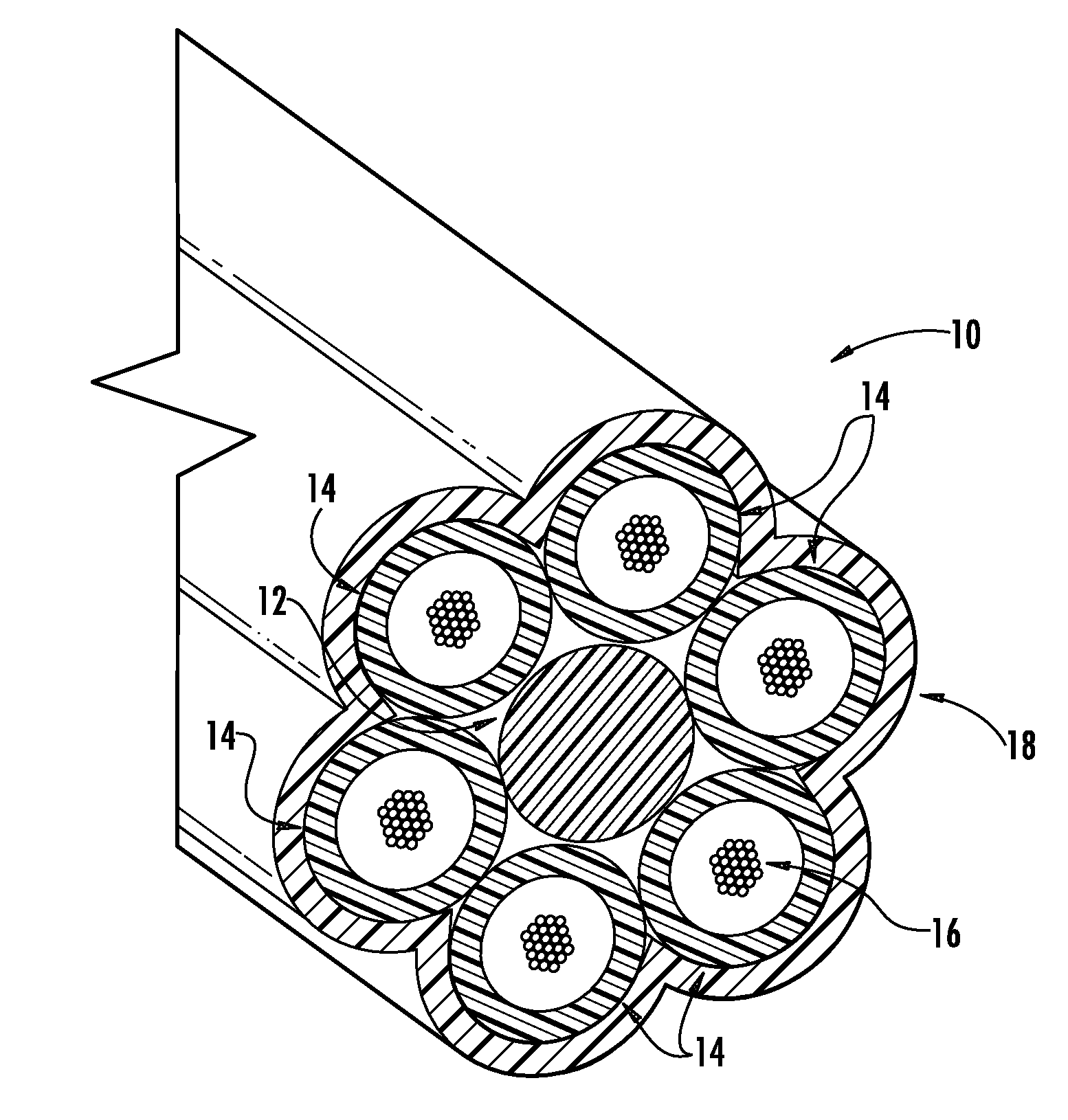
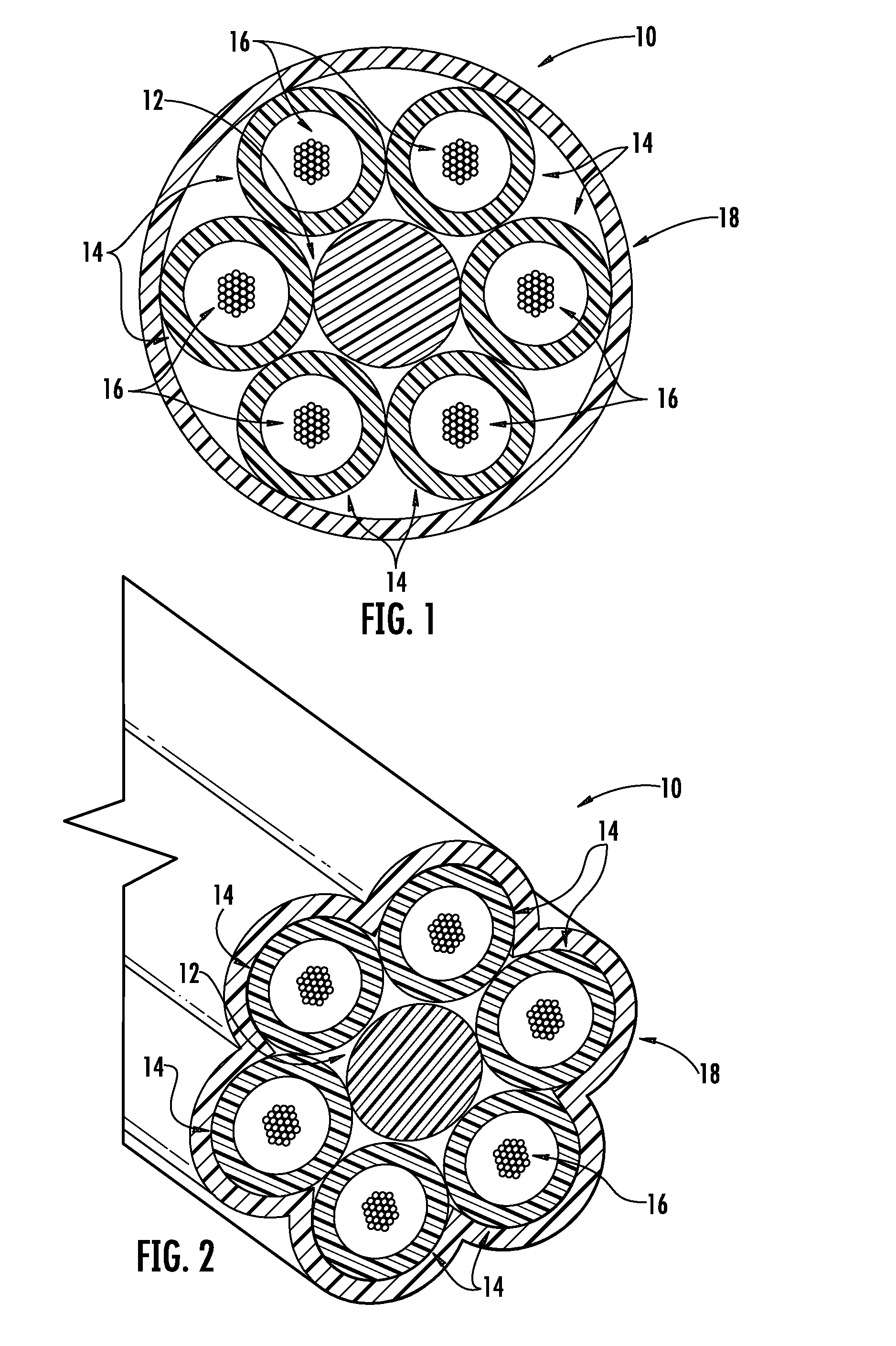
[0009]Accordingly, it is an object of the present invention to provide optical-fiber cables possessing high cable fiber densities while ensuring that the optical fibers enclosed therein demonstrate improved attenuation performance when subjected to temperature variations (e.g., between −40° C. and 70° C.).
[0010]It is another object of the present invention to provide optical-fiber cables that include standard single mode fibers (SSMF) at high packing densities (i.e., high fiber counts).
[0011]It is yet another object of the present invention to provide optical-fiber cables that include standard single mode fibers (SSMF) that are configured in buffer tubes within the cable in a way that promotes low attenuation.
[0012]It is yet another object of the present invention to provide optical-fiber cables that include standard single mode fibers (SSMF) that are capable of satisfactory mid-span storage over a wide range of temperatures.
[0013]It is yet another object of the present invention to provide optical-fiber cables that include at least 144 standard single mode fibers (SSMF) and that are configured in buffer tubes to provide reduced attenuation.
[0017]It is yet another object of the present invention to provide high-fiber-density optical-fiber cables (e.g., microcables) that can be readily pushed or blown into ducts or microducts to effect installation.

Problems solved by technology

Packing fibers into tight spaces can cause undesirable attenuation.
Such optical-fiber cables can achieve higher fiber densities, but the constituent buffer tubes have unsatisfactory mid-span storage performance as positioned in pedestals, cabinets, or other optical-fiber enclosures.
These temperature cycles can lead to signal attenuation.

Method used


Image

  • High-fiber-density optical fiber cable
  • High-fiber-density optical fiber cable

Examples


example

[0107]Table 1 (below) compares a comparative optical-fiber cable to an exemplary optical-fiber cable of the present invention.

[0108]

TABLE 1InventiveComparativeCableCablecable configurationbuffer tubes per cable612fibers per buffer tube2412optical-fibers per cable144144optical-fiber informationoptical-fiber diameter (μm)242242optical-fiber area (μm2)45,99645,996total optical-fiber area (mm2)6.6236.623buffer-tube informationtube outer diameter (mm)31.9tube inner diameter (mm)2.21.2buffer-tube area (mm2)3.8011.131total buffer-tube area (mm2)22.80813.572cable informationcable outer diameter (mm)10.511.1cable outer area (mm2)86.59096.769cable inner diameter (mm)9.39.9cable inner area (mm2)67.92976.977cable propertiescable filling coefficient (inner)0.0980.086outer cable filling coefficient0.0760.068cable fiber density (fibers / mm2)1.6631.488cumulative buffer tube0.2900.488filling coefficient

[0109]Both optical-fiber cables depicted in Table 1 contain 144 optical fibers and were designed to...


PUM


Abstract

Disclosed is a fiber-optic cable that possesses a high cable filling coefficient (and / or a high cable fiber density) yet ensures that its enclosed optical fibers demonstrate improved attenuation performance when subjected to temperature variations between about −40° C. and 70° C. The fiber-optic cable is suitable for efficient installation into ducts, such as via blowing.

Description

CROSS-REFERENCE TO PRIORITY APPLICATIONS[0001]This application claims the benefit of U.S. Patent Application No. 61 / 096,750 for a “High-Fiber-Density Optical Fiber Cable” (filed Sep. 12, 2008), and U.S. Patent Application No. 61 / 113,146 for a “High-Fiber-Density Optical Fiber Cable” (filed Nov. 10, 2008), each of which is incorporated by reference in its entirety.FIELD OF INVENTION[0002]The present invention relates to optical-fiber cables and, more generally, to electrical or other communication signal carriers. The present invention, for instance, embraces an optical-fiber cable design that is particularly suitable for blown installation into microducts.BACKGROUND OF THE INVENTION[0003]As compared with traditional wire-based networks, optical-fiber communication networks are capable of transmitting significantly more information at significantly higher speeds. Optical fibers, therefore, are being increasingly employed for communication networks.[0004]To expand total transmission t...

Claims


Application Information

Patent Timeline
Patent Type & Authority Patents(United States)
IPC IPC(8): G02B6/44
CPCG02B6/4411G02B6/4464G02B6/4438G02B6/52
Inventor LOVIE, RAYBARKER, JEFFREY SCOTTSMARTT, WILLIAM MARKOVERTON, BOB J.
Owner DRAKA COMTEQ BV
Learn More