Plug connector having unlocking mechanism

a technology of unlocking mechanism and plug connector, which is applied in the direction of coupling device connection, optical element, instrument, etc., can solve the problems of unfavorable conduction of forces, and complex structure of unlocking element, so as to achieve a simple and positive effect on the manufacturing cost of the connector

Active Publication Date: 2012-07-17
HUBERSUHNER AG
View PDF20 Cites 88 Cited by
  • Summary
  • Abstract
  • Description
  • Claims
  • Application Information

AI Technical Summary

Benefits of technology

[0026]As already mentioned above, US 2004/0247252 discloses a connector with a very complicated structure. Although this connector has a displaceable part, it cannot be compared, in respect of the structure and the manner of operation, with a connector according to the invention disclosed in this document, which, amongst other things, can be produced in a substantially simpler manner. The connector known from US 2004/0247252 has a displaceable rear part which forms the entire rear region of the connector. Depending on the embodiment, the displaceable part interacts with the locking arm by means of one or more short, steep ramps which are arranged in the interior of the housing. The ramps are arranged on a rigid, non-deformable structure. By displacing the rear part in relation

Problems solved by technology

One disadvantage is the unfavorable conduction of the forces: since a force which is directed forward is required for depressing the trigger, but a force which is directed toward the rear is required for removing the connector from a socket, the connector can be unlocked only with comparative difficulty.
One disadvantage is that the unlocking element has a very complicated structure.
One disadvantage of the solutions known from the prior art is the unfavorable conduction of forces during unlocking, and also the complicated structure.
Other plug connectors are distinguished by a complicated structure which has a disadvantageous effect on the manufacturing costs.
These force conditions are unfavorable since while one f

Method used


Image

  • Plug connector having unlocking mechanism
  • Plug connector having unlocking mechanism
  • Plug connector having unlocking mechanism

Examples


first embodiment

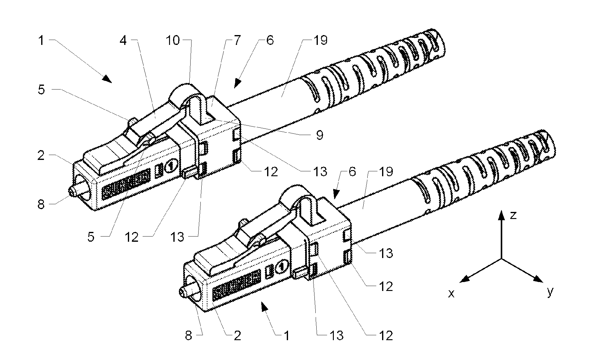
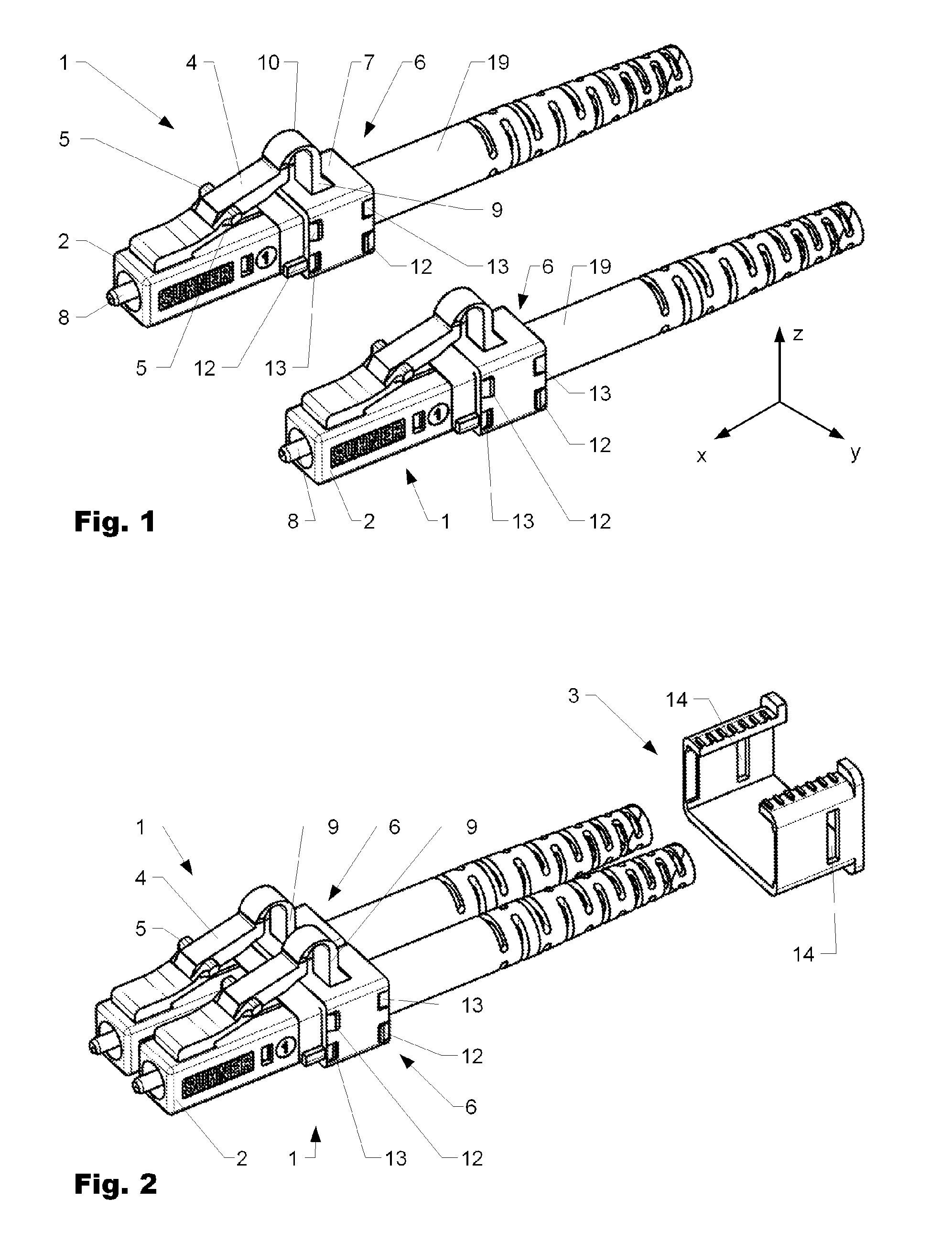
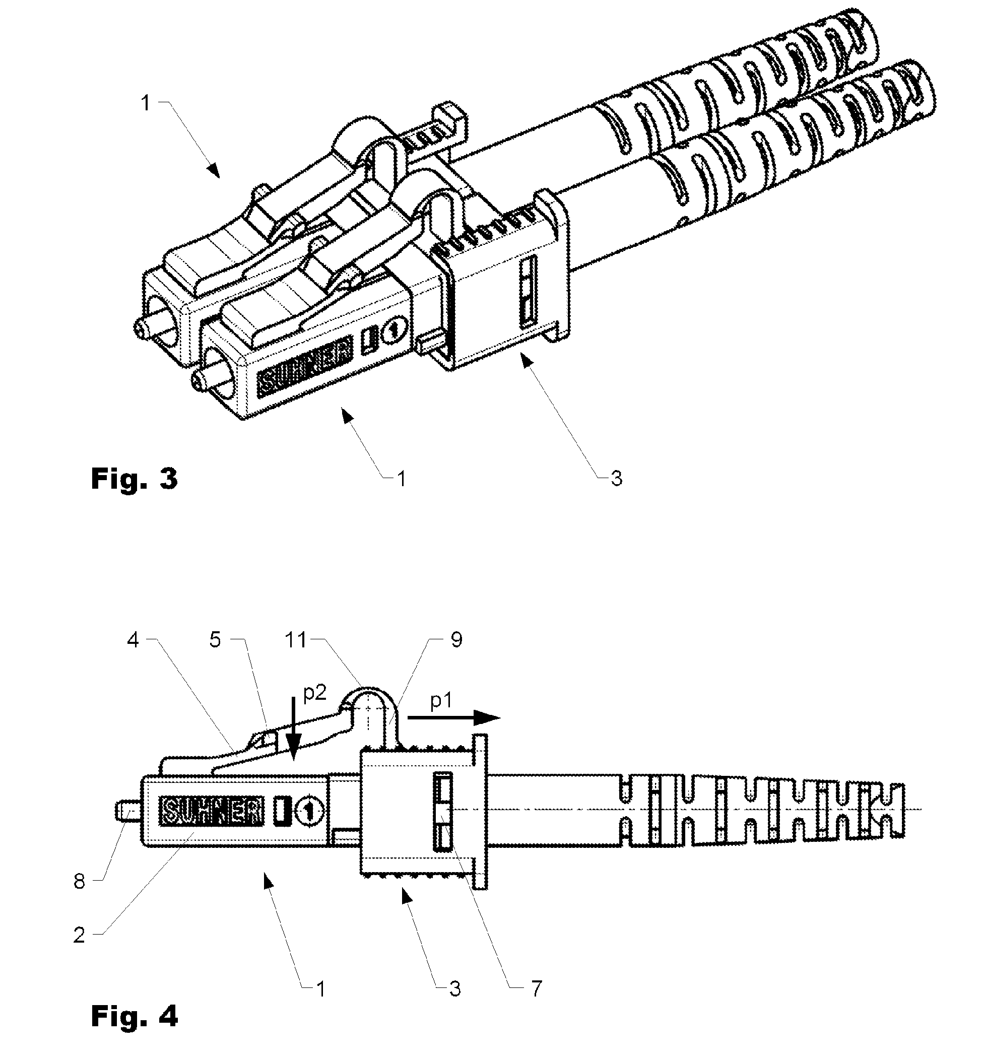
[0043]FIG. 1 shows two connectors 1 in a first embodiment side by side. FIG. 2 shows the connectors 1 according to FIG. 1 joined laterally, together with a connector clamp 3 which is not yet operatively connected. FIG. 3 shows a perspective illustration of the two connectors 1 according to FIG. 1 obliquely from the front and above. The connectors 1 are situated side-by-side and operatively connected by means of the connector clamp 3. FIG. 4 shows the connectors according to FIG. 3 from the side.

[0044]The connectors 1 have a base body 2 and a blocking arm 4 which protrudes in an elastically resilient manner obliquely toward the rear from the front end of the base body 1. Laterally projecting locking shoulders 5 are arranged on the locking arm 4 and serve to snap into corresponding recesses in a correspondingly designed socket (not illustrated). A ferrule 8 for accommodating and for connecting an optical conductor (not illustrated in any detail) can be seen at the front end of the bas...

third embodiment

[0058]FIG. 8 shows a perspective illustration of two connectors 1 of a third embodiment obliquely from above. FIG. 13 shows a plan view of the connectors 1 according to FIG. 8. FIG. 14 shows a section through the arrangement of FIG. 13 along section line AA. The two connectors 1 illustrated in FIGS. 8 and 13 are operatively connected to one another by means of a connector clamp 20 which simultaneously serves as an unlocking element 6.

[0059]FIG. 9 shows two connectors 1 according to FIG. 8 side-by-side. The connector 1 which is at the front as seen by the viewer is illustrated partially in section so that the internal structure can be seen more clearly. In contrast to the arrangement according to FIG. 8, each connector 1 has its own unlocking element 6. If required, the unlocking elements may have operative connection means (not illustrated further) by means of which two unlocking elements can additionally be operatively connected to one another.

[0060]The plug connectors 1 each have ...


PUM


Abstract

The present disclosure relates to an optical plug connector (1) having an improved unlocking mechanism. A locking arm (4), which protrudes toward the back in a slanted manner, is operatively connected to a collar (7) by way of a bracket (9). By displacing the collar (7) in an unlocking direction (−x), the connector (1) can be unlocked and removed from a sleeve.

Description

CROSS REFERENCE TO RELATED APPLICATIONS[0001]The present application is a 35 U.S.C. §371 National Phase conversion of PCT / EP2009 / 055161, filed Apr. 28, 2009, which claims benefit of Swiss Application No. 00707 / 08, filed May 7, 2008, the disclosures of which are incorporated herein by reference. The PCT International Application was published in the German language.BACKGROUND[0002]1. Field of the Disclosure[0003]The invention relates to the field of plug connectors, in particular plug connectors for optical cables.[0004]2. Related Art[0005]Plug connectors for optical cables are known from the prior art. So-called LC connectors are likewise known. In a further sense, these are push-pull connectors which have a high packing density. Corresponding connectors are manufactured by the applicant but are also available from a wide variety of other manufacturers.[0006]European patents EP 0 762 558 B1 and EP 0 768 547 B1 describe an optical plug connector. The plug connector has a base body fo...

Claims


Application Information

Patent Timeline
IPC IPC(8): G02B6/36
CPCG02B6/3893H01R13/633H01R13/6272
Inventor PETERHANS, ADRIANZAINA, PATRICKSCOPIC, NESA
Owner HUBERSUHNER AG
Why Eureka
Try Eureka