

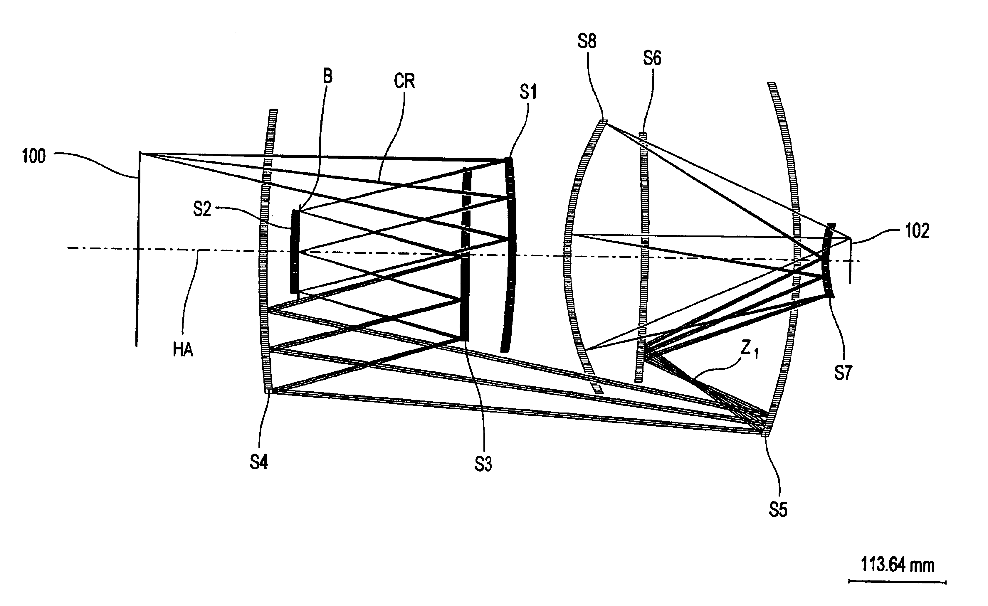
8-mirror microlithography projection objective
a microlithography and projection objective technology, applied in the field of microlithography objectives, can solve the problems of difficult interferometric testability, limited imaging of structures of a specific size, and few correction options for imaging errors
- Summary
- Abstract
- Description
- Claims
- Application Information
AI Technical Summary
Benefits of technology
Problems solved by technology
Method used
Image

Examples
Embodiment Construction
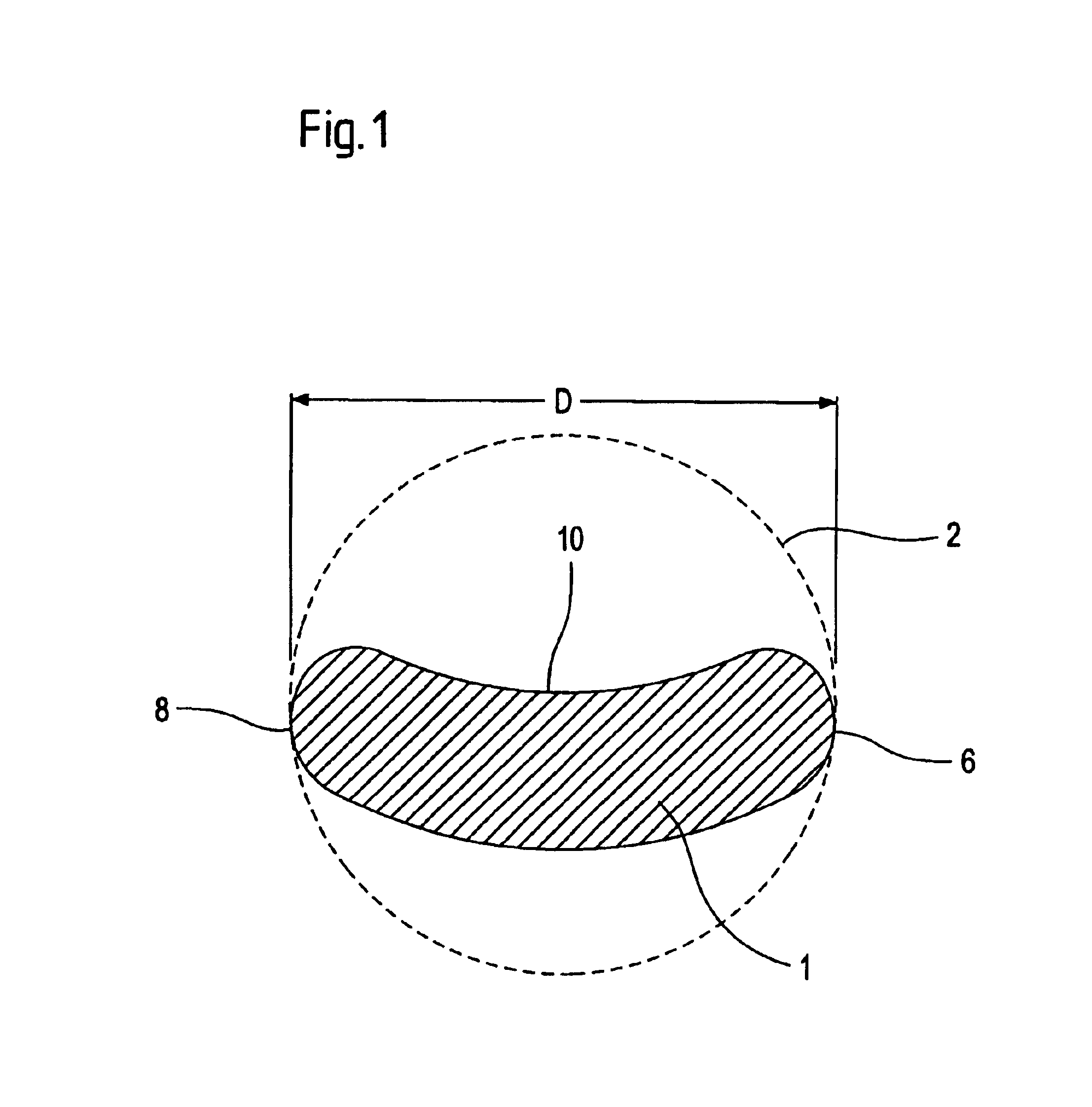
In FIG. 1 is shown what is to be understood in the present application as off-axis segments of a mirror and the diameter of such an off-axis segment.
FIG. 1 shows a kidney-shaped field as an example of a projected field 1 on a mirror of the projection objective. Such a shape is expected for the off-axis segments in an objective according to the invention, if used in a microlithography projection exposure system. The enveloping circle 2 completely encloses the kidney shape and coincides with edge 10 of the kidney shape at two points 6, 8. The enveloping circle is always the smallest circle that encloses the off-axis segment. Diameter D of the off-axis segment then results from the diameter of enveloping circle 2.
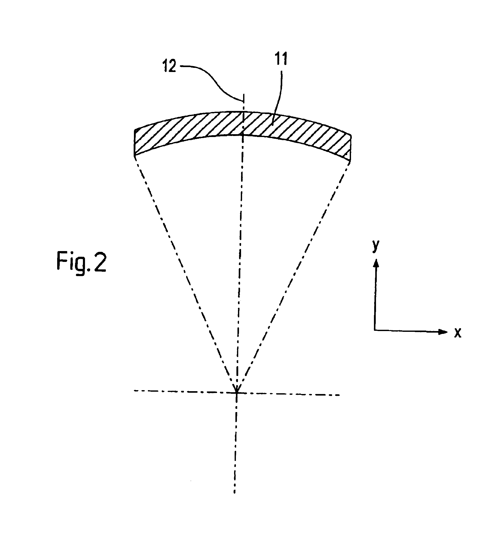
In FIG. 2, the object field 11 of a projection exposure system is shown in the object plane of the projection objective, which is imaged by means of the projection objective according to the invention in an image plane, in which a light-sensitive object, for example, a wafer i...
PUM
| Property | Measurement | Unit |
|---|---|---|
| wavelength | aaaaa | aaaaa |
| angle of incidence | aaaaa | aaaaa |
| wavelengths | aaaaa | aaaaa |
Abstract
Description
Claims
Application Information