Heat pipe with composite capillary wick structure

Inactive Publication Date: 2007-10-18
HON HAI PRECISION IND CO LTD
View PDF21 Cites 57 Cited by
  • Summary
  • Abstract
  • Description
  • Claims
  • Application Information

AI Technical Summary

Problems solved by technology

However, this single-type, uniform wick 20 generally cannot provide optimal heat transfer effect for t

Method used


Image

  • Heat pipe with composite capillary wick structure
  • Heat pipe with composite capillary wick structure
  • Heat pipe with composite capillary wick structure

Examples


Embodiment Construction

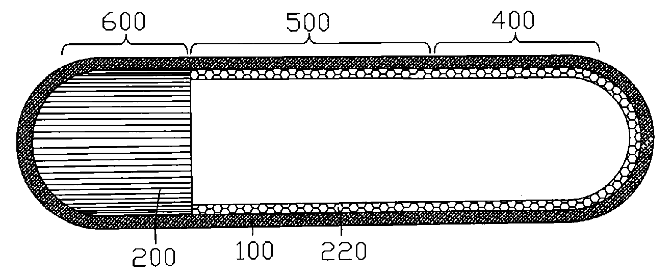
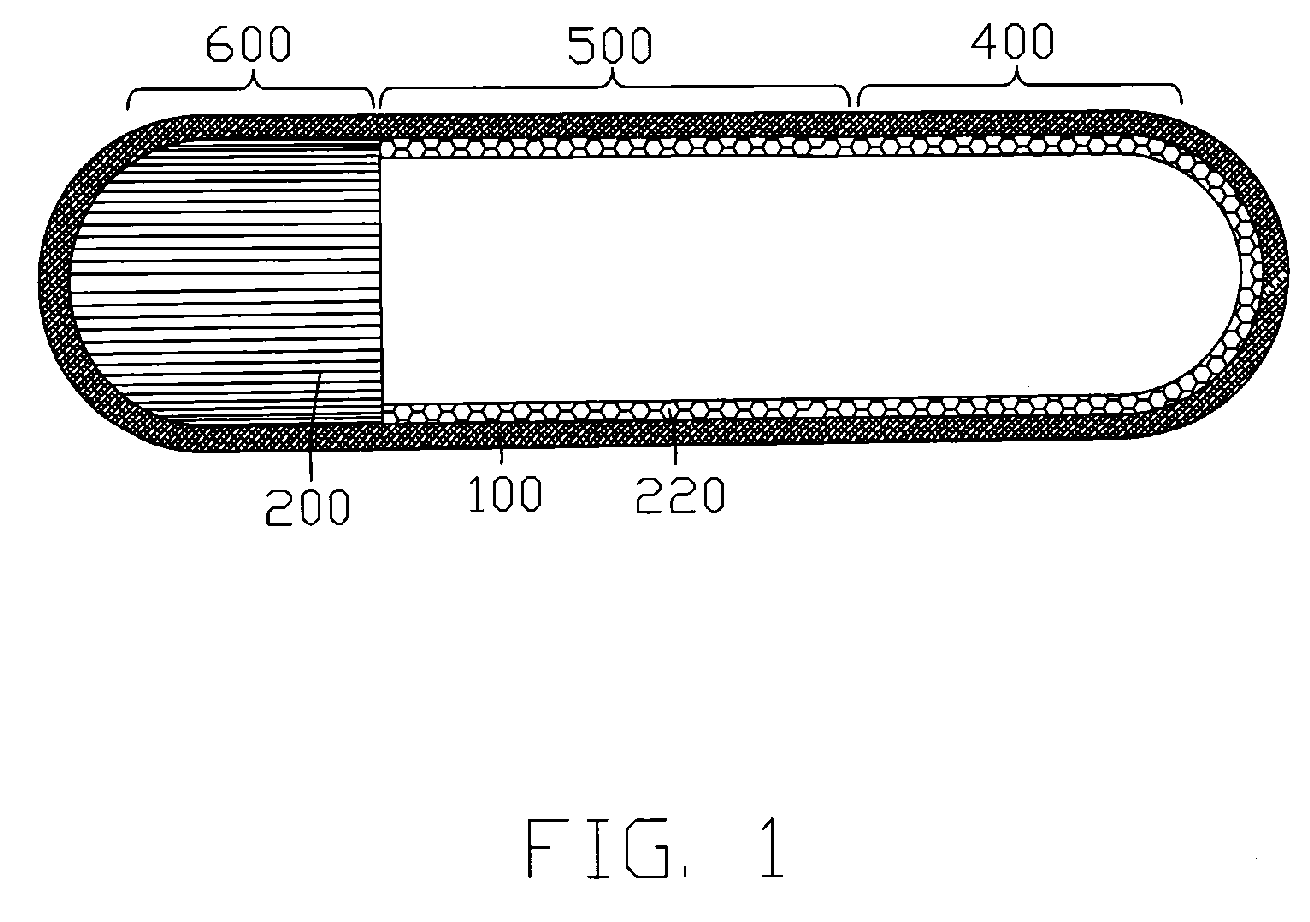
[0014]FIG. 1 illustrates a heat pipe in accordance with a first embodiment of the present invention. The heat pipe comprises a casing 100 and a composite capillary wick (not labeled) arranged on an inner wall of the casing 100. The casing 100 comprises an evaporating section 400 at one end and a condensing section 600 at an opposite end thereof, and a central section (i.e., adiabatic section) 500 located between the evaporating section 400 and the condensing section 600. The casing 100 is made of highly thermally conductive materials such as copper or copper alloys and filled with a working fluid (not shown), which acts as a heat carrier for carrying thermal energy from the evaporating section 400 to the condensing section 600. Heat that needs to be dissipated is transferred firstly to the evaporating section 400 of the casing 100 to cause the working fluid therein to evaporate. Then, the heat is carried by the working fluid in the form of vapor to the condensing section 600 where t...


PUM


Abstract

A heat pipe includes a metal casing (100) and a composite capillary wick received in the casing. The metal casing has an evaporating section (400), a condensing section (600) and a central section (500) between the evaporating section and the condensing section. First type of capillary wick (200) is provided on an inner all of the metal casing at all of the condensing, central and evaporating sections, while second type of capillary wick (220) is provided on the first type of capillary wick at the central and evaporating sections only. A capillary pore size of the first type of capillary wick is larger than that of the second type of capillary wick.

Description

1. FIELD OF THE INVENTION[0001]The present invention relates generally to a heat transfer apparatus, and more particularly to a heat pipe having a composite capillary wick structure.2. DESCRIPTION OF RELATED ART[0002]As a heat transfer apparatus, heat pipes can transfer heat rapidly and therefore are widely used in various fields for heat dissipation purposes. Fox example, in electronic field, heat pipes are commonly applied to transfer heat from heat-generating electronic components, such as central processing units (CPUs), to heat dissipating devices, such as heat sinks, to thereby remove the heat away. A heat pipe in accordance with related art generally includes a sealed casing made of thermally conductive material and a working fluid contained in the casing. The casing includes an evaporating section at one end and a condensing section at the other end. The working fluid is employed to carry heat from the evaporating section to the condensing section of the casing. Specifically...

Claims


Application Information

Patent Timeline
IPC IPC(8): F28D15/00
CPCF28D15/046
Inventor HOU, CHUEN-SHULIU, TAY-JIANHE, QIAN-HUASUN, CHIH-HSIENTUNG, CHAO-NIEN
Owner HON HAI PRECISION IND CO LTD
Why Eureka
Try Eureka