Surgical trocar

a surgical and trocar technology, applied in the field of trocars, can solve the problems of difficult to pull out, and dangerous sharp end of the trocar, and achieve the effect of reducing the snagging or tearing of the patient's skin

a surgical and trocar technology, applied in the field of trocars, can solve the problems of difficult to pull out, and dangerous sharp end of the trocar, and achieve the effect of reducing the snagging or tearing of the patient's skin

US20090204140A1Inactive Publication Date: 2009-08-13DANDL JOHN E

Image

  • Surgical trocar
  • Surgical trocar
  • Surgical trocar

Examples


Embodiment Construction

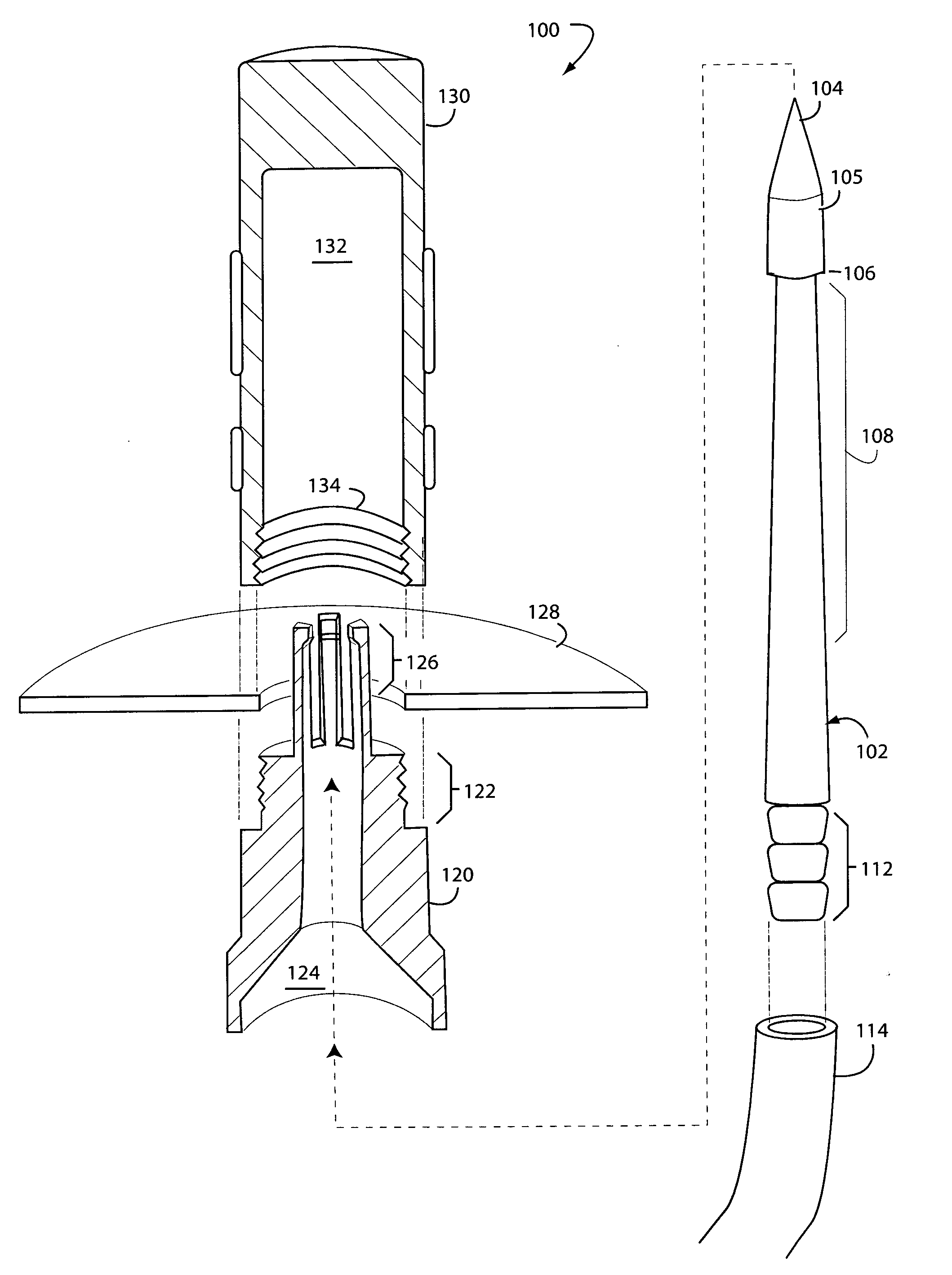
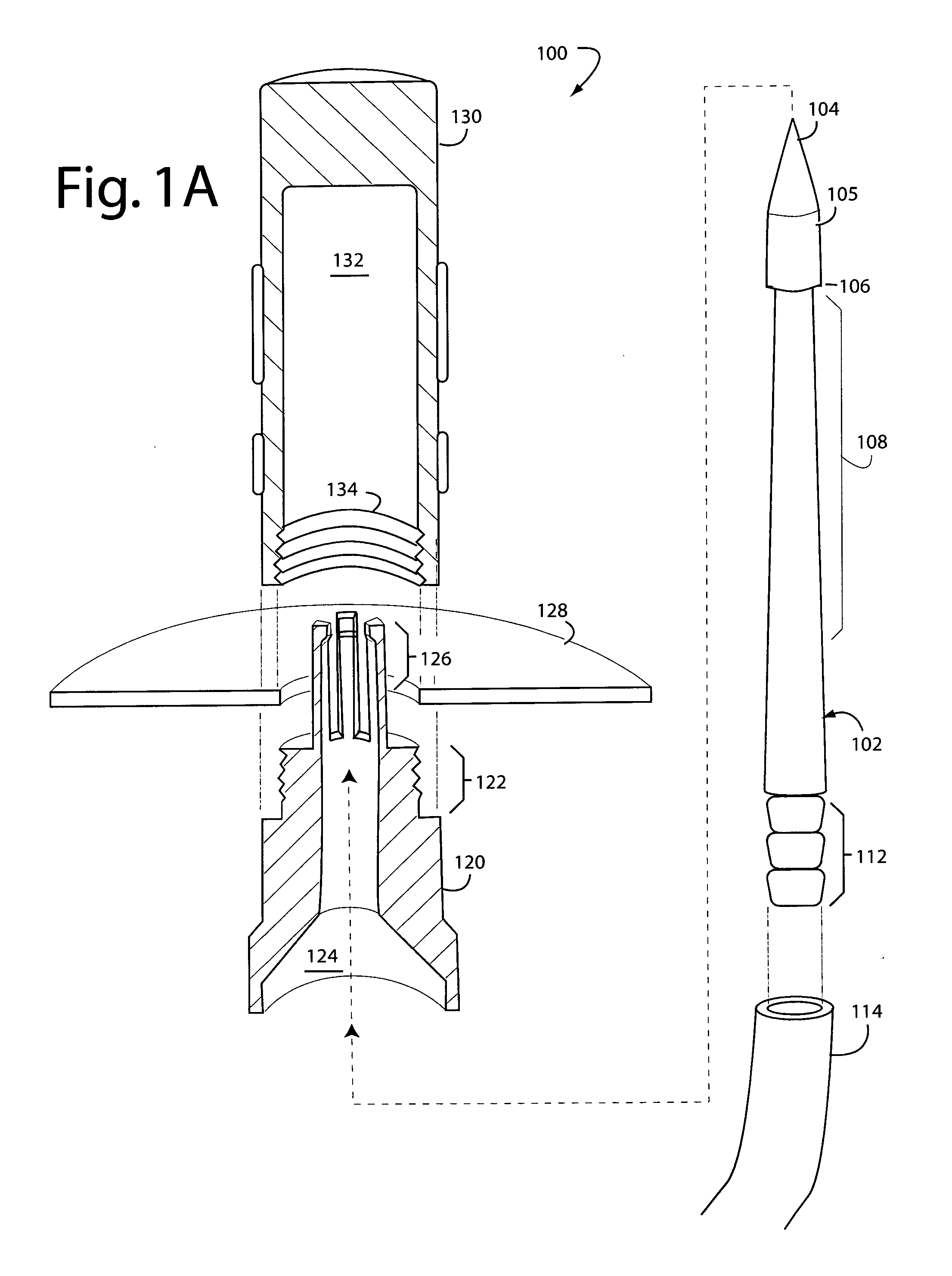
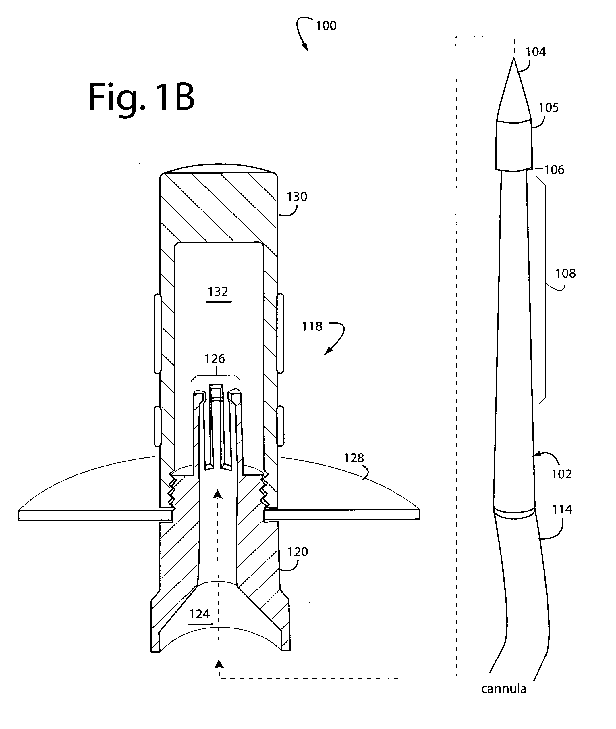
[0016]FIGS. 1A-1C represent a surgical trocar system embodiment of the present invention, and is referred to herein by the general reference numeral 100. Trocar system 100 comprises a straight or slightly curved trocar needle 102 with a sharp tip 104 that forms a head 105 with a ridge 106. A tapered section 108 gradually increases back in diameter to the size of the head 105 in the direction of a hose barb 112. In one embodiment, such tapered section was 3-mm in diameter increasing to 5-mm in diameter over a distance of 40-mm. The trocar needle was 150-mm in overall length. A drain tubing 114 provides a way to drain a surgical site after closure and suturing.

[0017]The tapered section 108 is important in that there is no groove formed aft of the ridge 106 that can snag and tear the patient's skin when the needle 102 is being pushed through by a surgeon.

[0018]A trocar receiver 118 (FIG. 1C) is assembled from three parts that screw together. A base 120 includes a threaded collar 122, a...


PUM


Abstract

A surgical trocar includes a trocar needle with a sharp tip for puncturing and passing through the skin of a patient. A hose barb disposed on a distal end of the trocar needle retains a drain tubing while they are being threaded through a skin puncture. A head formed aft of the tip of the trocar needle has a locking ridge to provide a grip. A tapered section of the trocar needle is disposed aft of the head and has its minimum diameter adjacent to the locking ridge, and its maximum diameter in the direction of the hose barb. Thus, a gradually increasing diameter of the tapered section aft of the head substantially reduces any snagging or tearing of a patient's skin around an associated skin puncture during use.

Description

BACKGROUND OF THE INVENTION[0001]1. Field of the Invention[0002]The present invention relates to surgical trocars, and in particular to trocars designed to puncture and pass through skin and provide a drain after surgery without snagging or tearing the skin around the puncture.[0003]2. Description of Related Art[0004]Wikipedia defines a trocar as a hollow cylinder with a sharply pointed end, often three-sided, that is used to introduce cannulas and other similar implements into blood vessels or body cavities. Trocars are also used as ports in laparoscopic surgery.[0005]The trocar is often passed inside a cannula, and functions as a portal for the subsequent placement of other devices, such as a chest drain, intravenous cannula, etc. Surgical trocars are used for laparoscopic surgery. They can be a means of introduction for laparoscopic hand instruments, e.g., scissors and graspers, to do surgery previously done by making a large abdominal incision. Surgical trocars are usually a sin...

Claims


Application Information

Patent Timeline
13 Aug 2009
Publication
US20090204140A1
IPC
A61B17/34; A61M27/00
CPC
A61B17/3415; A61B2019/4805; A61B2017/3454; A61B17/3417; A61B2090/0801
Inventors
DANDL, JOHN E.; SUDERMAN, DONALD P.