Fixing device and image forming apparatus

Inactive Publication Date: 2009-08-20
SHARP KK
View PDF5 Cites 12 Cited by
  • Summary
  • Abstract
  • Description
  • Claims
  • Application Information

AI Technical Summary

Benefits of technology

[0013]An object of the invention is to provide a fixing device capable of preventing conveyance of a recording medium from being impeded in the presence of variation in a drive load on a fixing roller, as well as to provide an image forming apparatus having the fixing device.

Problems solved by technology

The technique disclosed in JP-A 9-286529 is thus not applicable to the fixing device.

Method used


Image

  • Fixing device and image forming apparatus
  • Fixing device and image forming apparatus
  • Fixing device and image forming apparatus

Examples


Embodiment Construction

[0049]Now referring to the drawings, preferred embodiments of the invention will be described in detail.

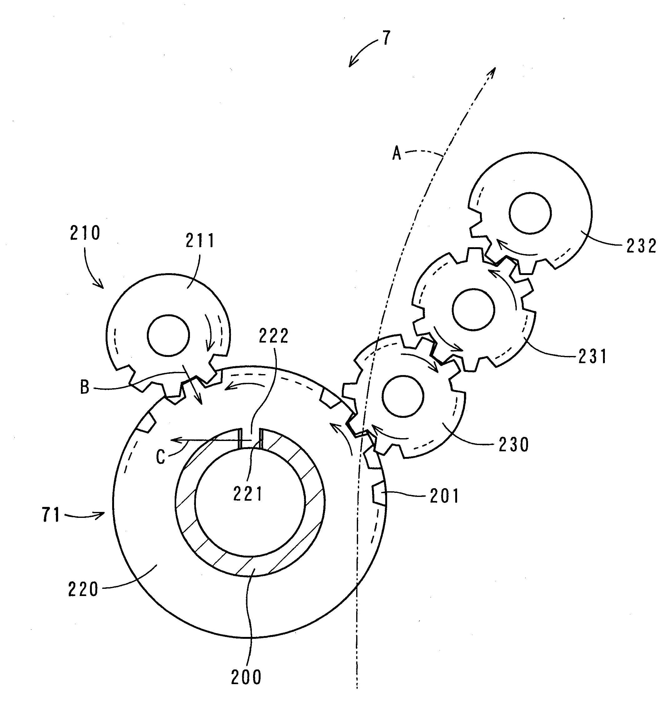
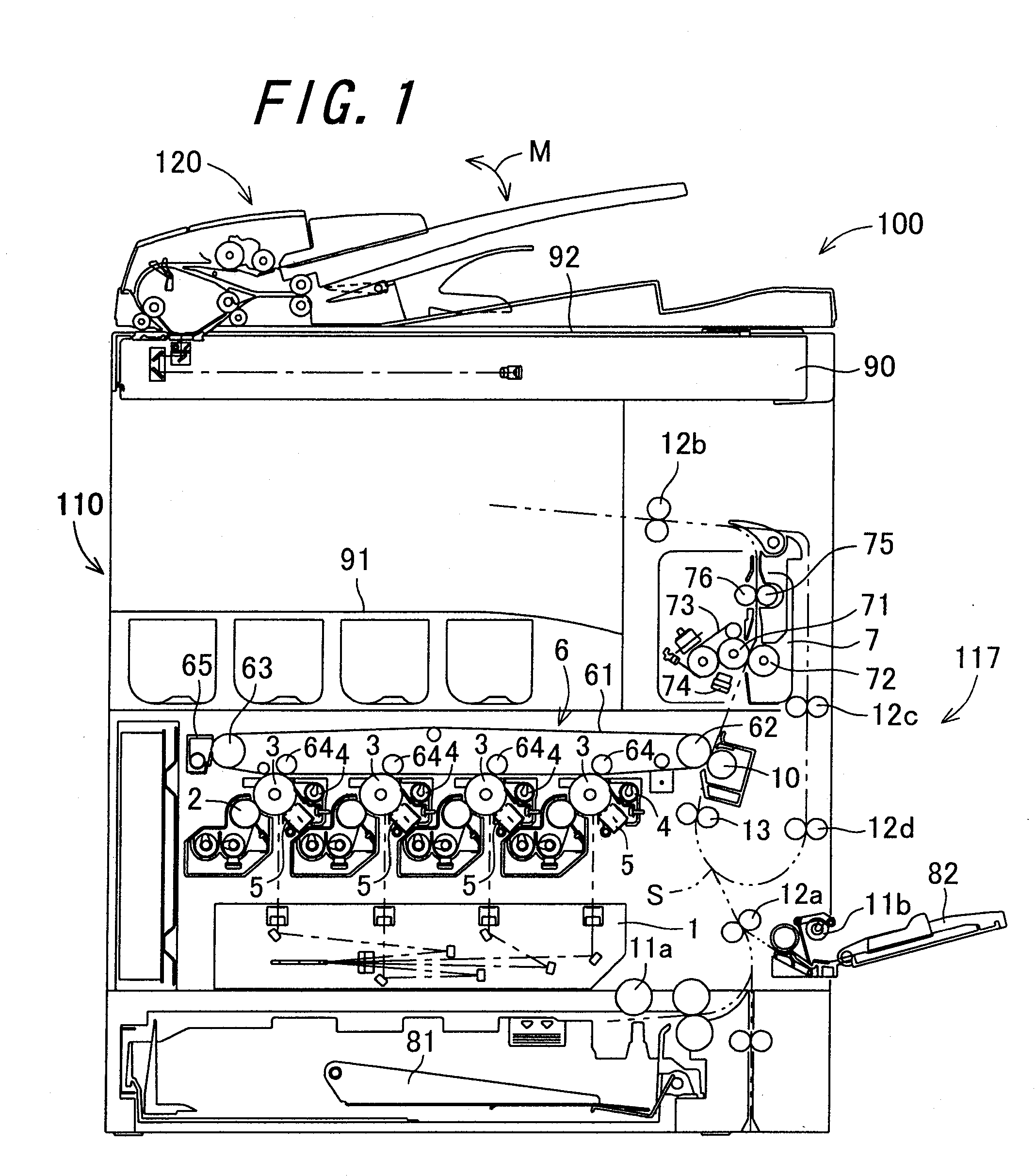
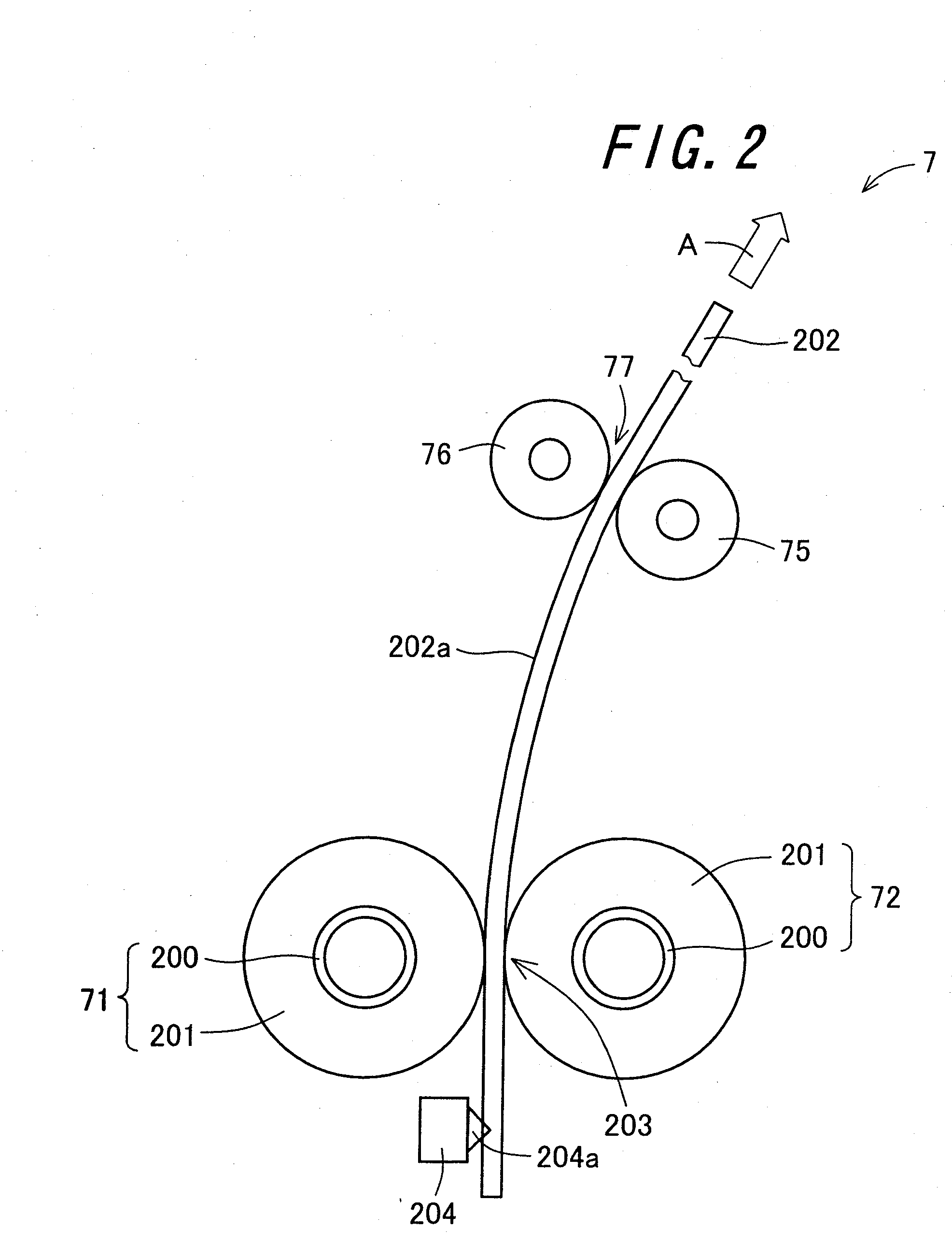
[0050]FIG. 1 is a schematic diagram showing the structure of an image forming apparatus 100 having a fixing unit7 which is a fixing device according to one embodiment of the invention. The image forming apparatus 100 is designed to form multi-color or one-color images on a predetermined recording medium, for example, a sheet-like recording medium such as recording paper (hereafter also referred to as “recording sheet”) in accordance with externally-transmitted image data. The image forming apparatus 100 comprises an apparatus main body 110 and an automatic document processing device 120. The apparatus main body 110 comprises an image reading section 90, an exposure unit 1, a developing device 2, a photoreceptor drum 3, a cleaner unit 4, a charging device 5, an intermediate transfer belt unit 6, a fixing unit 7, a paper-feeding cassette 81, a manual paper-feeding cassette 82, and a...


PUM


Abstract

In a fixing unit, a fixing roller is rotated under driving force transmitted from a paper discharge unit-side gear of a driving section via a fixing roller driving gear, and holds and conveys a recording medium in cooperation with a pressure roller in a nip region. When a control section determines that acceleration conditions are fulfilled, the driving section increases the rotating speed of the paper discharge unit-side gear so that it is rotated at higher speed than before-acceleration speed over predetermined high-speed rotating period.

Description

CROSS-REFERENCE TO RELATED APPLICATION[0001]This application claims priority to Japanese Patent Application No. 2008-035352, which was filed on Feb. 15, 2008, the contents of which are incorporated herein by reference in its entirety.BACKGROUND OF THE INVENTION[0002]1. Field of the Invention[0003]The present invention relates to a fixing device for fixing a toner image formed on a recording medium onto the recording medium, as well as to an image forming apparatus having the fixing device.[0004]2. Description of the Related Art[0005]An electrophotographic image forming apparatus for forming images by means of electrophotography, such as a copying machine and a printer, is provided with a fixing device. As the fixing device, as shown in FIG. 2 for explaining the invention which will hereafter be described, there is known a fixing device 7 having a heat roller 71 which is heated by a heating portion and a pressure roller 72 which is brought into contact with the heat roller 71 under a...

Claims


Application Information

Patent Timeline
IPC IPC(8): G03G15/20
CPCG03G15/2064G03G2215/00738G03G2215/00721G03G15/657
Inventor KATSURA, NORICHIKATANIGUCHI, TADASUFUJITA, MASAHIKOKIMURA, MASAHARU
Owner SHARP KK
Why Eureka
Try Eureka