
Image forming apparatus with toner refilling unit

a technology of toner refilling unit and forming apparatus, which is applied in the direction of electrographic process apparatus, instruments, optics, etc., can solve the problem of reducing the possibility of apparatus determination, and achieve the effect of reducing the amount of toner discharged, enhancing the possibility of successfully detecting that toner remains in the hopper, and evenly leveling

Inactive Publication Date: 2017-05-23
COPYER
View PDF17 Cites 3 Cited by
  • Summary
  • Abstract
  • Description
  • Claims
  • Application Information

AI Technical Summary

Benefits of technology

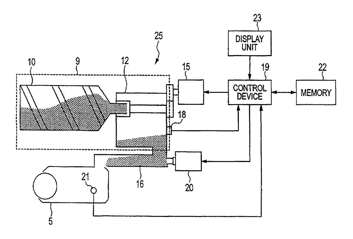
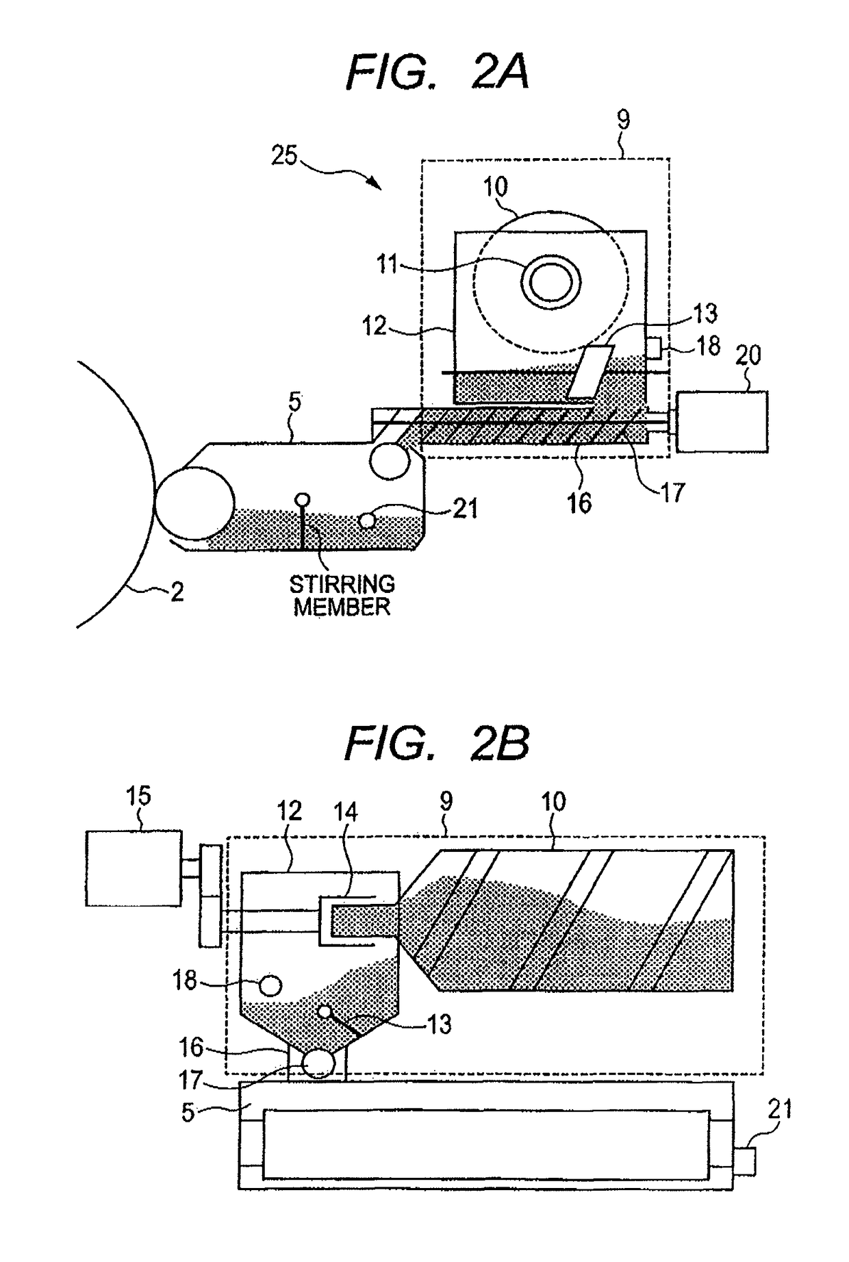
[0016]If no toner is detected in the hopper in spite of the toner refilling operation performed by rotating the toner bottle by the unit amount after the toner-in-hopper detecting unit has detected that no toner remains in the hopper, the rotation of the toner bottle by the unit amount is repeated. In this case, the number of executions reaching the predetermined threshold means the reduced amount of toner remaining in the toner bottle. When the number of executions reaches the predetermined threshold, the apparatus drives the conveying unit and thus the stirring member instead of immediately determining that no toner remains in the toner bottle. Even after the stirring member has been driven, the apparatus determines that no toner remains in the toner bottle when the toner-in-hopper detecting unit detects that no toner remains in the hopper. That is, when the toner in the hopper converges in the vicinity of an outlet of the toner bottle, the apparatus may determine that no toner remains in the hopper even though toner actually remains in the hopper. Such erroneous detection of emptiness is avoided by driving the stirring member to allow the toner-in-hopper detecting unit to detect the toner.
[0017]The control unit can variably set the predetermined threshold based on an accumulated value obtained by accumulating the number of executions after replacement of the toner bottle. For example an increase in accumulated value means a decrease in the amount of toner remaining in the toner bottle. Thus, an increase in accumulated value reduces the amount of toner discharged from the toner bottle based on the rotation of the toner bottle by the unit amount. To compensate for this, the threshold is increased in a stepwise fashion consistently with the accumulated value. Then, the number of operations of refilling the hopper with toner from the toner bottle is increased when the toner-in-hopper detecting unit detects that no toner remains in the hopper. This reduces the possibility that the apparatus determines that no toner remains in the hopper in spite of driving of a hopper motor, compared to the case in which the threshold is not increased.
[0018]The image forming apparatus according to the present invention may further include an amount-of-toner-in-developing-unit detecting unit for detecting the amount of toner in the developing unit. In this case, the control unit checks an output from the amount-of-toner-in-developing-unit detecting unit when the number of executions reaches the predetermined threshold. The control unit then inhibits the conveying unit from being driven when the output is equal to or larger than a predetermined value. Thus allows toner to be inhibited from being conveyed when the amount of toner in the developing unit exceeds a predetermined value. As a result, the developing unit is prevented from being refilled with an excessive amount of toner.
[0020]The time for which the conveying unit is driven according to each of at least the first and second thresholds may be varied depending on the magnitude of the threshold. The larger threshold is expected to reduce the amount of toner discharged from the toner bottle. Thus, the possibility of successfully detecting that toner remains in the hopper can be enhanced by increasing the time for which the hopper motor is driven, that is, the time for stirring.
[0021]The apparatus may further include a unit configured to detect that the toner bottle has been replaced. In this case, the control unit drives the conveying unit when the hopper is refilled with toner by at least the first rotation of the toner bottle by the unit amount after the replacement Of the toner bottle. It is expected that a large amount of toner remains in the toner bottle after the replacement of the toner bottle, causing a significantly large amount of toner to be discharged from the toner bottle during the first rotation of the toner bottle by the unit amount. Even in such a case, the toner in the hopper can be evenly leveled by driving the conveying unit. This avoids smudging the inside of the apparatus with toner, enabling the user's hand or clothes to be prevented from being stained when the toner bottle is replaced.
[0022]The present invention prevents the toner bottle from being erroneously determined to be empty, thus reducing the amount of toner remaining in the tone bottle when the apparatus shows that the toner bottle is empty. The present invention also enables the user to be notified of the amount of toner remaining in the toner bottle without the need to newly provide an additional detecting unit.

Problems solved by technology

This reduces the possibility that the apparatus determines that no toner remains in the hopper in spite of driving of a hopper motor, compared to the case in which the threshold is not increased.

Method used


Image

  • Image forming apparatus with toner refilling unit
  • Image forming apparatus with toner refilling unit
  • Image forming apparatus with toner refilling unit

Examples


Embodiment Construction

[0035]Preferred embodiments of the present invention will now be described in detail in accordance with the accompanying drawings.

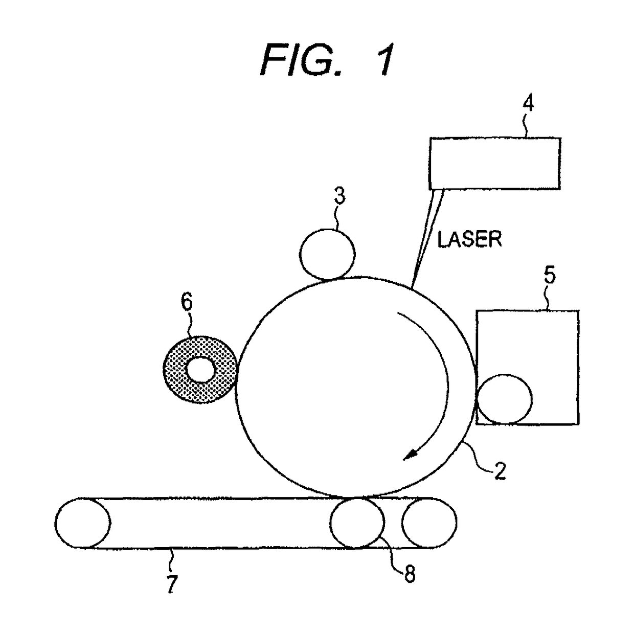
[0036]FIG. 1 schematically illustrates the configuration of an electrophotographic image forming apparatus according to the present exemplary embodiment. The image forming apparatus includes a photosensitive drum (image carrier) 2 configured to rotate in the direction of an arrow illustrated in FIG. 1, and in its periphery, charging member 3 configured to charge the photosensitive drum 2 to a predetermined potential, an image writer 4 such as a laser scanner which is configured to write an electrostatic latent image to the photosensitive drum 2, a developing unit 5 configured to visualize the electrostatic latent image formed on the photosensitive drum 2 using toner, a cleaner 6 configured to remove toner located on the surface of the photosensitive drum 2 and not transferred, and a transfer unit. The transfer unit includes a transfer belt 7 on which a tr...


PUM


Abstract

The present invention prevents a toner bottle from being erroneously determined to be empty and allows toner to be reliably refilled into a hopper and thus a developing unit in an image forming apparatus including the developing unit configured to develop an electrostatic latent image formed on an image carrier, using toner.

Description

BACKGROUND OF THE INVENTION[0001]Field of the Invention[0002]The present invention relates to an image forming apparatus such as an electrophotographic copier, and in particular, to an image forming apparatus in which toner is refilled via a replaceable toner bottle.[0003]Description of the Related Art[0004]In recent years, electrophotographic copiers and information recording apparatuses have been increasingly miniaturized. Thus, a plurality of developing units is provided in a limited space around an electrostatic latent image carrier or the size of a developing unit is reduced. As a result, the amount of toner housed in the developing unit is also reduced.[0005]Thus, in some image forming apparatuses, developing unit is refilled with toner fed directly from a storage vessel (hereinafter referred to as a toner bottle) filled with the toner. In this configuration, the amount of toner discharged into the developing unit is not constant owing to the amount of toner remaining in the t...

Claims


Application Information

Patent Timeline
Patent Type & Authority Patents(United States)
IPC IPC(8): G03G15/08
CPCG03G15/0877G03G15/0872G03G15/0839
Inventor KAYAHARA, YASUFUMI
Owner COPYER
Learn More