Developing unit and image forming apparatus including the same

a technology of developing unit and image forming apparatus, which is applied in the direction of electrographic process apparatus, instruments, optics, etc., can solve the problems of uneven density of toner on a formed image, increase in the thickness of the thin layer of increase in the thickness of the toner on the development roller. , to achieve the effect of improving the quality of an image formed and stabilizing the thickness

Active Publication Date: 2010-08-31
KYOCERA DOCUMENT SOLUTIONS INC
View PDF3 Cites 4 Cited by
  • Summary
  • Abstract
  • Description
  • Claims
  • Application Information

AI Technical Summary

Benefits of technology

[0015]An object of the present invention is to provide a developing unit capable of reliably removing toner on a development roller to minimize development history while reducing accumulation of a developer to prevent carriers from being conveyed to the development roller and to prevent the interior of an image forming apparatus from being soiled with the developer by appropriately forming a magnetic brush. Another object of the present invention is to provide an image forming apparatus capable of forming a good-quality and stable image by using the developing unit.
[0017]Since a magnetic brush can be appropriately formed in the developing unit, toner can be reliably removed from a development roller to minimize development history while reducing accumulation of a developer to prevent carriers from being conveyed to the development roller and to prevent the interior of an image forming apparatus from being soiled with the developer.
[0019]By using the developing unit in the image forming apparatus, the quality of an image formed can be improved and stabilized.

Problems solved by technology

If formation of the toner thin layer is continued, non-uniformity in the thickness of the toner thin layer on the development roller increases.
As a result, the density of toner on a formed image becomes uneven and images formed earlier may appear (development history).
However, if the binding force of the magnetic brush is weak, toner remaining on the development roller is not completely removed, which can cause development history.
The accumulated developer can cause the problem that carriers are conveyed to the development roller together with toner.
When developer further accumulates to an excessive amount, developer can spill over or out of the developing unit and make the interior of the image forming apparatus dirty.
These problems can degrade an image formed.
In this way, the magnetic brush formed in the gap between the magnetic roller and the development roller significantly affects the quality of an image formed.
Consequently, a problem arises that carriers are conveyed onto the development roller 64 together with toner.
Another problem arising is that when the developer further accumulates, a significant amount of the developer can spill out of the developing unit to soil the interior of the image forming apparatus.
Furthermore, while the conventional developing unit can ensure a uniform thickness of the thin layer of toner formed, the developing unit does not adequately remove residual toner.
Consequently, it is difficult to prevent development history.

Method used


Image

  • Developing unit and image forming apparatus including the same
  • Developing unit and image forming apparatus including the same
  • Developing unit and image forming apparatus including the same

Examples


Embodiment Construction

[0028]An embodiment of the present invention will be described with reference to FIGS. 1 to 6. The embodiment will be described with respect to an electrophotography-based tandem full-color image forming apparatus. Configurations, arrangements, and other elements given in the description of the present embodiment are not limitative but illustrative.

[0029]An overview of the image forming apparatus including a developing unit according to one embodiment of the present invention will be described first with reference to FIGS. 1 and 2.

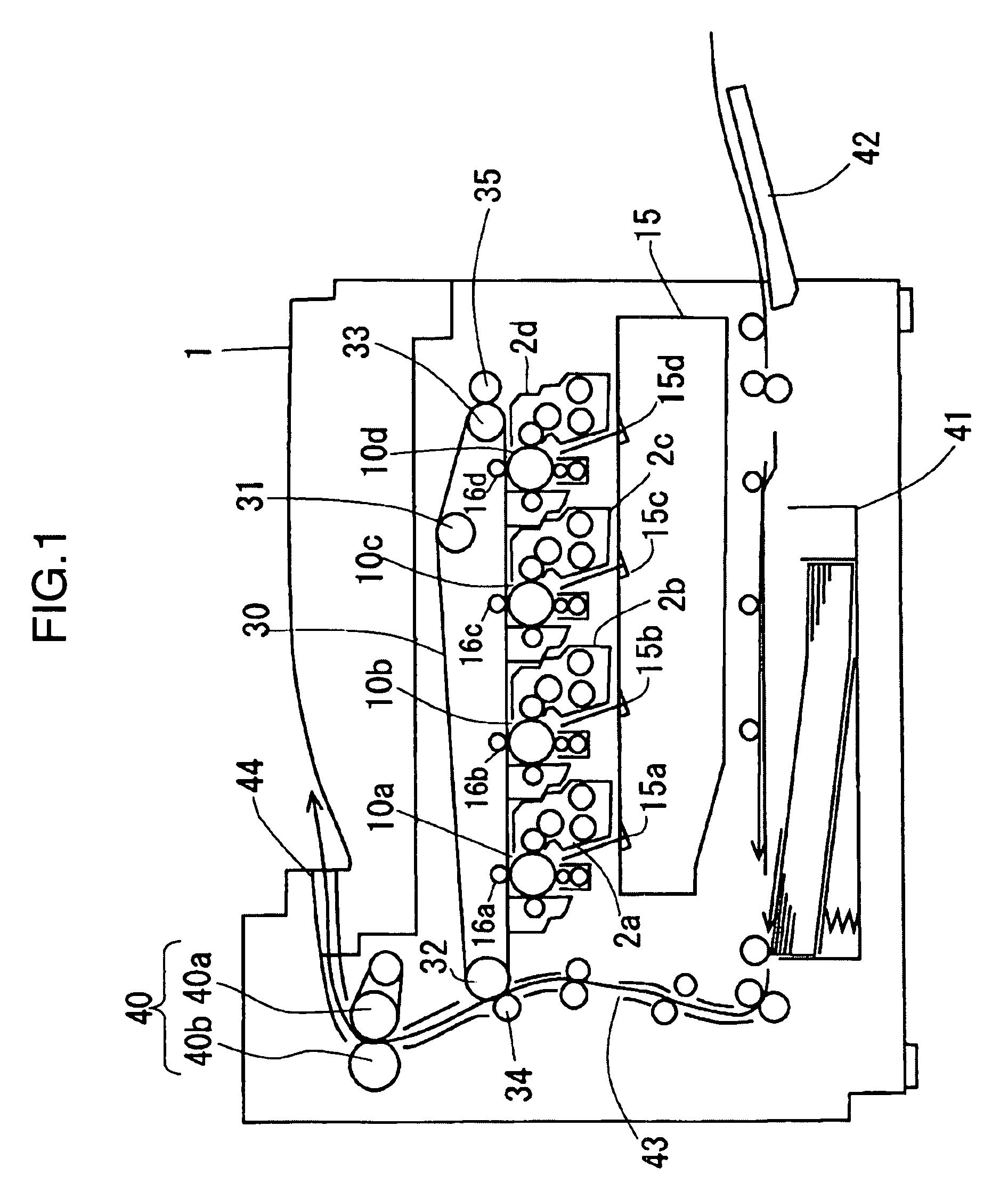
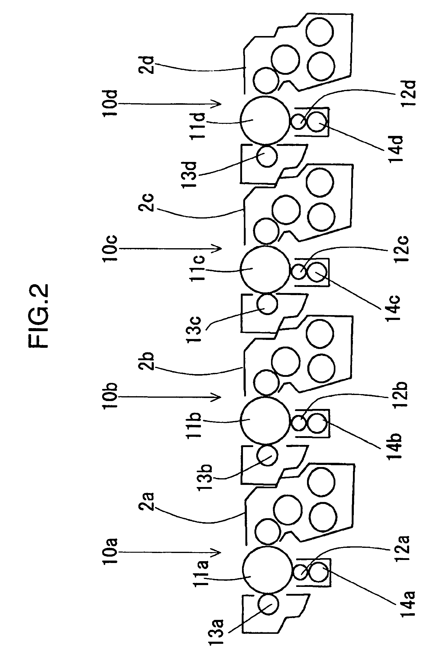
[0030]FIG. 1 is a cross-sectional view schematically showing a configuration of an image forming apparatus according to one embodiment of the present invention, viewed from the front. FIG. 2 is an enlarged cross-sectional view of an image forming section of the image forming apparatus shown in FIG. 1.

[0031]As shown in FIGS. 1 and 2, the image forming apparatus 1 includes an image forming section 10a that forms a black image, an image forming section 10b th...


PUM


Abstract

A developing unit includes a development roller and a magnetic roller. Sleeves of the development roller and the magnetic roller are driven to rotate in the same circumferential direction. A first magnet is provided on the roller shaft in the sleeve of the development roller and a second magnet is provided on the roller shaft in the sleeve of the magnetic roller. The first and second magnets are opposed to each other so that opposite polarities face each other, and are supported non-rotatably in circumferential directions. The first magnet is supported so that the peak of the magnetic force of the first magnet is positioned upstream in the direction of rotation of the sleeve of the development roller from the straight line connecting the center of the roller shaft of the development roller to the center of the roller shaft of the magnetic roller.

Description

BACKGROUND OF THE INVENTION[0001]1. Field of the Invention[0002]The present invention relates to a developing unit used in an image forming apparatus such as a copying machine, printer, and facsimile machine, and to an image forming apparatus including the developing unit.[0003]2. Description of the Related Art[0004]Image forming apparatuses based on electrophotography are available generally that use a two-component developer consisting primarily of carriers and toner to develop an image. In this method, the developing unit includes a magnetic roller containing a magnet member. The magnetic roller holds the developer and forms a magnetic brush with carriers. The magnetic brush is brought into contact with an image carrier to supply toner to the image carrier.[0005]There is another system for developing an image using a two-component developer in which two rollers, a magnetic roller and a development roller, are provided in a developing unit. In this system, the magnetic roller cont...

Claims


Application Information

Patent Timeline
Patent Type & Authority Patents(United States)
IPC IPC(8): G03G15/09
CPCG03G15/0808G03G15/0921G03G2215/0609
Inventor NAKAUE, TAKAHISASAKATA, SHOICHI
Owner KYOCERA DOCUMENT SOLUTIONS INC
Why Eureka
Try Eureka