Vibration device

a technology of vibration device and lens, which is applied in the direction of mechanical vibration separation, mounting, instruments, etc., can solve the problem that water droplets inside the field of view of the camera and attached to the lens cannot be reliably removed, and achieve the effect of reliably removing water droplets and reliable removal

Active Publication Date: 2020-02-06
MURATA MFG CO LTD
View PDF0 Cites 8 Cited by
  • Summary
  • Abstract
  • Description
  • Claims
  • Application Information

AI Technical Summary

Benefits of technology

[0016]In a vibration device according to a preferred embodiment of the present invention, the vibration device further includes a piezoelectric vibrator that is a piezoelectric element other than the piezoelectric element, and the piezoelectric vibrator provides a vibration mode that is one of a vibration mode in which the piezoelectric vibrator vibrates the cylindrical body in a direction that connects the inner surface and the outer surface to each other and a vibration mode in which the piezoelectric vibrator vibrates the cylindrical body in a direction that connects the first end portion and the second end portion to each other. In this case, water droplets and the like attached to the surface of the light-transmitting body inside the field of view of the imaging device are able to be more reliably removed.
[0017]According to the preferred embodiments of the present invention, vibration devices that are each able to reliably remove water droplets and the like that are inside the field of view of an imaging device and attached to the surface of a light-transmitting body located on the subject side of an imaging element are provided.

Problems solved by technology

In the camera having the water-droplet-removing function as described in Japanese Unexamined Patent Application Publication No. 2013-080177, there are cases where water droplets that are inside the field of view of the camera and attached to the lens cannot be reliably removed.

Method used


Image

  • Vibration device
  • Vibration device
  • Vibration device

Examples


Embodiment Construction

[0032]Hereafter, the present invention will be made clearer by describing specific preferred embodiments of the present invention with reference to the drawings.

[0033]The preferred embodiments described in the present specification are illustrative examples and portions of the configurations illustrated in different preferred embodiments are able to be substituted for one another or combined with one another.

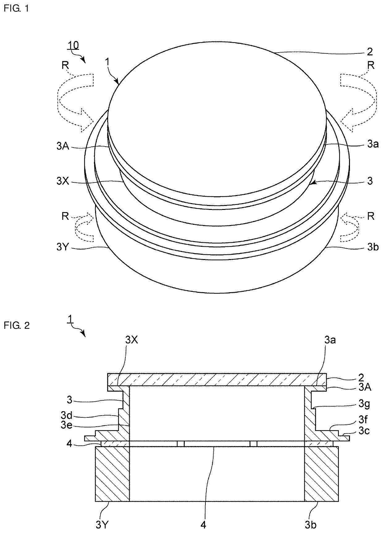
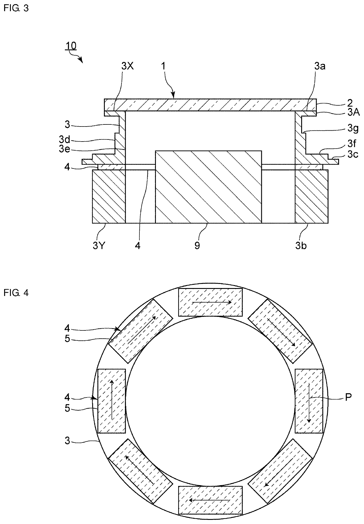
[0034]FIG. 1 is a perspective view of a vibration device according to a first preferred embodiment of the present invention. FIG. 2 is a front sectional view of the vibration device according to the first preferred embodiment. FIG. 3 is a front sectional view of an imaging device that includes the vibration device of the first preferred embodiment.

[0035]As illustrated in FIGS. 1 and 2, a vibration device 1 includes a light-transmitting body 2. As illustrated in FIG. 3, in an imaging device 10, the light-transmitting body 2 is located on a subject side of an imaging element 9, th...


PUM


Abstract

A vibration device includes a light-transmitting body that is located on a subject side of an imaging element, a cylindrical body that includes a first end portion, a second end portion on the opposite side from the first end portion, and an outer surface and an inner surface that connect the first end portion and the second end portion to each other, the cylindrical body being connected to the light-transmitting body and holding the light-transmitting body on the first end portion side thereof, and a piezoelectric element provided along a circumferential direction of the cylindrical body and that torsionally vibrates the cylindrical body.

Description

CROSS REFERENCE TO RELATED APPLICATIONS[0001]This application claims the benefit of priority to Japanese Patent Application No. 2017-089410 filed on Apr. 28, 2017 and is a Continuation Application of PCT Application No. PCT / JP2017 / 044348 filed on Dec. 11, 2017. The entire contents of each application are hereby incorporated herein by reference.BACKGROUND OF THE INVENTION1. Field of the Invention[0002]The present invention relates to a vibration device capable of removing water droplets and the like through mechanical vibration.2. Description of the Related Art[0003]Heretofore, there has been a demand for the field of view to be always clear in imaging devices, such as cameras used as surveillance devices. In particular, various mechanisms for removing water droplets such as raindrops have been proposed for cameras used outdoors such as in automotive applications. Japanese Unexamined Patent Application Publication No. 2013-080177 discloses a camera having a water-droplet-removing fun...

Claims


Application Information

Patent Timeline
Patent Type & Authority Applications(United States)
IPC IPC(8): B06B1/06
CPCB06B1/0648B06B1/045G02B7/02G03B17/08G02B27/0006G03B2205/0061B06B1/0625H04N23/52H10N30/208
Inventor FUJIMOTO, KATSUMIHORIGUCHI, CHIKAHIRONISHIYAMA, KENJIKURATANI, YASUHIROICHIGUCHI, SHINICHIRO
Owner MURATA MFG CO LTD
Why Eureka
Try Eureka