Method for manufacturing magnetic recording medium

a manufacturing method and magnetic recording technology, applied in the manufacture of record carriers, magnetic layer coatings, record carrier forms, etc., can solve the problems of deteriorating the magnetic characteristics of the recording layer, the limit of the head processing technology, and the limitation of the areal density improvement method, etc., to achieve high precision and remove reliably

Inactive Publication Date: 2008-04-03
TDK CORPARATION
View PDF7 Cites 30 Cited by
  • Summary
  • Abstract
  • Description
  • Claims
  • Application Information

AI Technical Summary

Benefits of technology

[0058]According to various exemplary embodiments of the present invention, the recording layer can be processed into a desired concavo-convex pattern with high precision, and the resin layer can be removed reliably, thoroughly, and efficiently.

Problems solved by technology

However, problems such as limitations with respect to the head processing technology, recording of data to the wrong track, which is adjacent to the target track, due to the spread of the recording magnetic field, and crosstalk during reproducing have emerged, and the improvement of the areal density by conventional improvement methodology has now reached its limit.
The CO gas added to the nitrogen-containing gas is likely to cause the process temperature to rise during the processing of the recording layer made of a magnetic material and to therefore deteriorate the magnetic characteristics of the recording layer.
A halogen-containing gas such as Cl2 and the like can oxidize or corrode the magnetic materials and, hence, is also likely to deteriorate magnetic characteristics of the recording layer.
Since a dry etching technique using a noble gas does not accompany a chemical reaction with the layer to be processed, it is hard to make much difference between the etching rates of the layer to be processed and the mask layer may not result.
However, the etching rate of carbon is relatively low for IBE using a noble gas and comes to approximately ¼ to ⅕ of the etching rate of the magnetic material.
Consequently, this can result in a resin layer which is significantly thick partly.
In such a case, there are concerns about the resin remaining in the finished product.
Moreover, portions of the resin layer remaining over the recording elements may cause a variety of problems during later processes such as a filler depositing step, a flattening step, and the like.
Therefore, if a processing time for the main mask layer processing step is extended to a duration such that the resin layer, whose thickness is significantly large at some locations, can be thoroughly removed, then the etching of the main mask layer in the width direction of the concave portion may become excessive.
This results in the concave portion whose width is inappropriately enlarged, causing problems associated with degraded processing precision of the recording layer.
However, such an arrangement exposes the recording layer to the oxygen-containing gas or the halogen-containing gas for an extended period of time so that oxidation or corrosion of the recording layer progresses to deteriorate its magnetic characteristics.
In particular, if the recording layer contains a non-oxide based magnetic material, the deterioration of its magnetic characteristics becomes significant.
However, if a wet etching step is to be carried out between the dry etching steps for processing respective layers, then the manufacturing steps as well as the manufacturing facilities become complicated, thereby significantly reducing production efficiency.
Furthermore, when the object to be processed is being taken out of the vacuum chamber or the like, problems associated with contamination by foreign objects or oxidation of the recording layer are likely to occur, deteriorating the reliability of the product.

Method used


Image

  • Method for manufacturing magnetic recording medium
  • Method for manufacturing magnetic recording medium
  • Method for manufacturing magnetic recording medium

Examples


working example

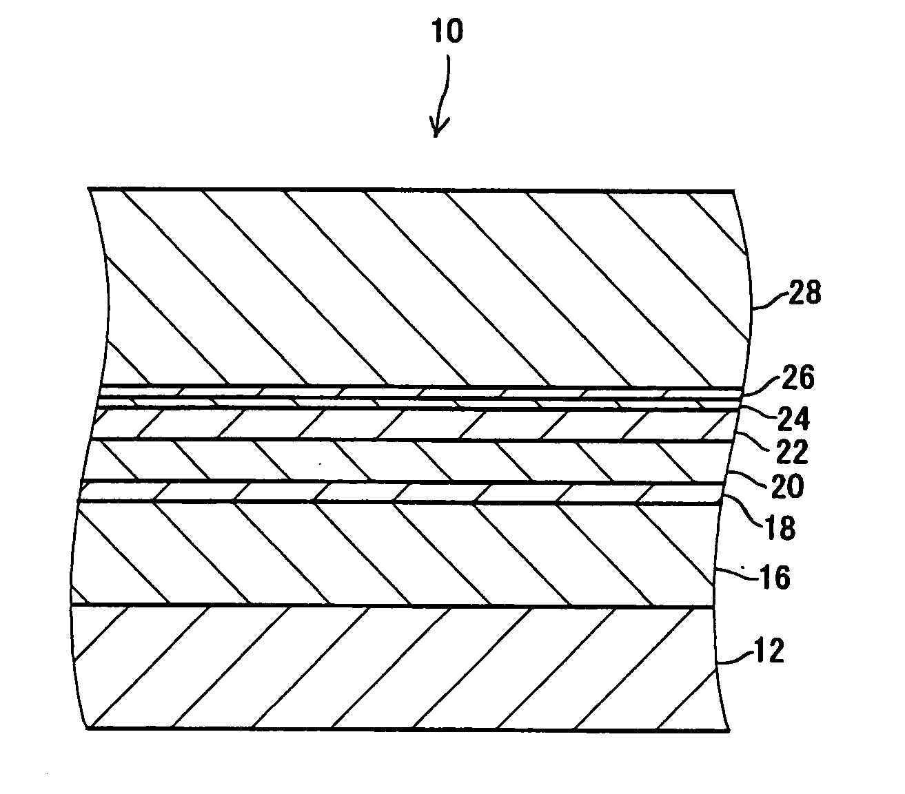
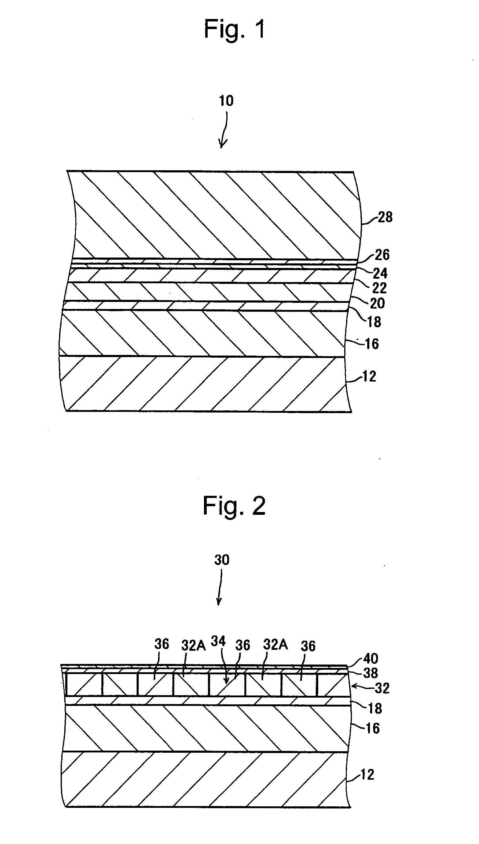
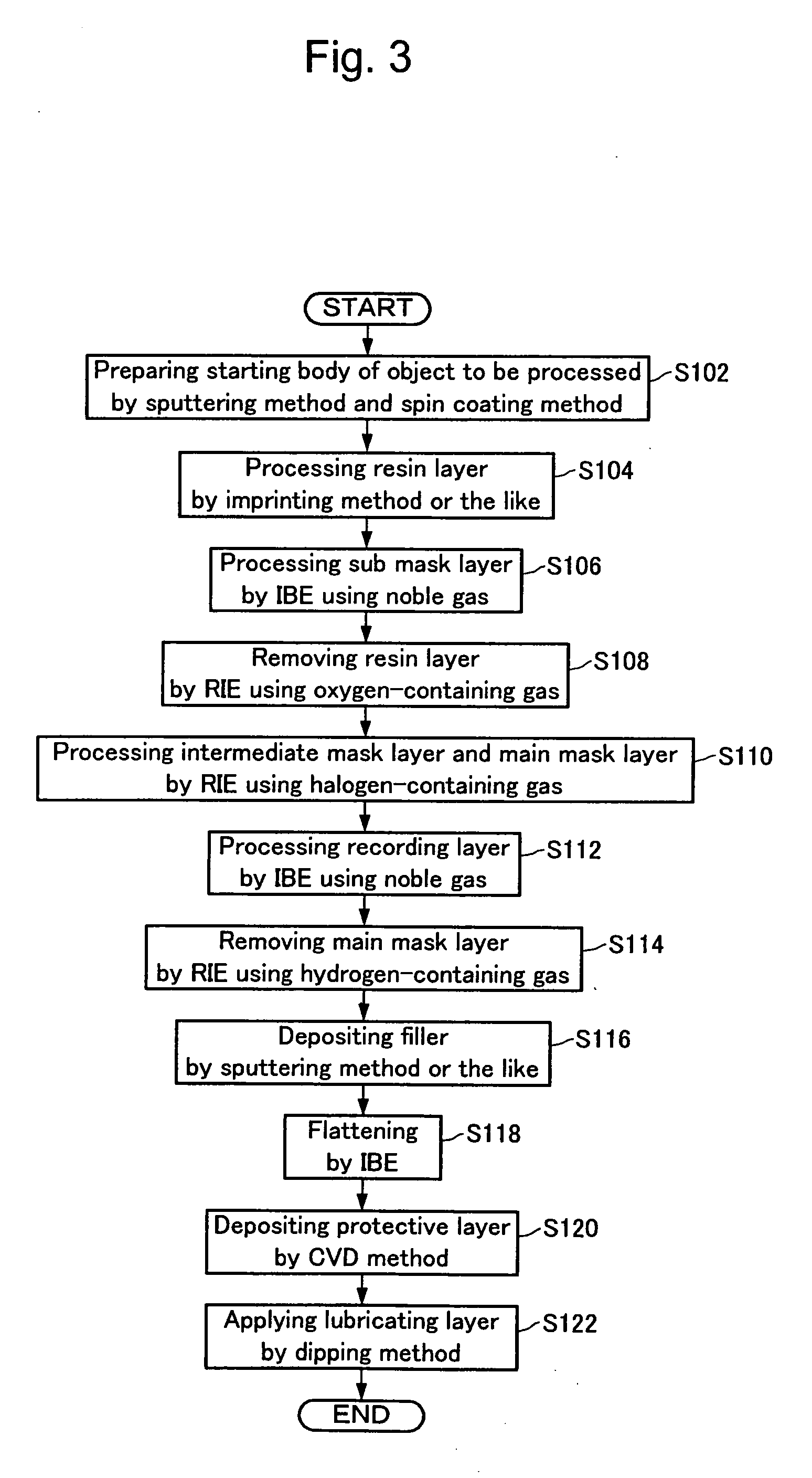
[0120]The magnetic recording medium 30 was manufactured as described in the first exemplary embodiment. Specifically, the starting body of the object to be processed 10 was prepared (S102).

[0121]The substrate 12 had a thickness of 0.6 mm and an outer diameter of 48 mm. The diameter of the center hole was 12 mm. The substrate 12 was made of glass.

[0122]The soft magnetic layer 16 had a thickness of 100 nm and was made of a CoZrNb alloy.

[0123]The seed layer 18 had a thickness of 30 nm and was made of Ru.

[0124]The recording layer 20 (32) had a thickness of 20 nm and was made of a CoCrPt alloy.

[0125]The main mask layer 22 had a thickness of 12 nm and was made of C (carbon).

[0126]The intermediate mask layer 24 had a thickness of 3 nm and was made of Si.

[0127]The sub-mask layer 26 had a thickness of 2 nm and was made of Ni.

[0128]The resin layer 28 had a thickness of 70 nm and was made of an acrylic resin. The resin layer 28 was formed by a spin coating method, where the resin was applied o...


PUM

PropertyMeasurementUnit
thicknessaaaaaaaaaa
thicknessaaaaaaaaaa
thicknessaaaaaaaaaa

Abstract

A method for manufacturing a magnetic recording medium with excellent production efficiency is provided in which the recording layer can be processed into a desired concavo-convex pattern with high precision and the resin layer can reliably and thoroughly be removed. A sub-mask layer having corrosion resistance against an oxygen-containing gas is provided over a main mask layer composed mainly of carbon. Furthermore, an intermediate mask layer is provided between the main mask layer and the sub-mask layer. The intermediate mask layer has corrosion resistance against the oxygen-containing gas, and its etching rate is higher for a halogen-containing gas than for the oxygen-containing gas. The resin layer removing step is conducted between the sub-mask layer processing step and the intermediate mask layer processing step (the main mask layer processing step). The resin layer removing step uses the oxygen-containing gas, and the intermediate mask layer processing step uses the halogen-containing gas.

Description

BACKGROUND OF THE INVENTION[0001]1. Field of the Invention[0002]The present invention relates to a method for manufacturing a magnetic recording medium having a recording layer formed in a concavo-convex pattern.[0003]2. Description of the Related Art[0004]Recently, a magnetic recording medium such as a hard disk and the like has undergone a number of improvements including a reduction in size of the magnetic particles constituting a recording layer, development of new materials, and heightened precision with regard to the processing of the head assembly. Because of these improvements, areal density has been significantly improved, and even further improvement thereof is expected in the future.[0005]However, problems such as limitations with respect to the head processing technology, recording of data to the wrong track, which is adjacent to the target track, due to the spread of the recording magnetic field, and crosstalk during reproducing have emerged, and the improvement of the ...

Claims


Application Information

Patent Timeline
Patent Type & Authority Applications(United States)
IPC IPC(8): B44C1/22
CPCB82Y10/00G11B5/855G11B5/82G11B5/743
Inventor HIBI, MIKIHARUFUJITA, MINORUHATTORI, KAZUHIRO
Owner TDK CORPARATION
Why Eureka
Try Eureka