Apparatus for manufacturing sheet glass

a technology for glass and glass ribbons, applied in glass tempering apparatuses, glass rolling apparatuses, manufacturing tools, etc., can solve the problems of difficulty in obtaining sheet glass with high precision, and inability to form glass ribbons

Inactive Publication Date: 2009-09-03
ASAHI GLASS CO LTD
View PDF23 Cites 9 Cited by
  • Summary
  • Abstract
  • Description
  • Claims
  • Application Information

AI Technical Summary

Benefits of technology

[0010]The present invention has been proposed in consideration of such circumstances. It is ail object of the present invention to provide an apparatus for manufacturing thin sheet glass which is capable of drastically easing known limitations to the viscosity of glass that glass, which is likely to be devitrified, cannot be formed by the overflow fusion process, and which is capable of easily forming even special glass having a high devitrification temperature, such as glass to be used as—a substrate for a flat panel display or information recording medium.
[0011]It is another object of the present invention to provide an apparatus for manufacturing thin sheet glass, which is capable of reliably removing distortion remaining in glass since it is possible to ensure a sufficient annealing time without need of a tall building and an operation space extending long in a vertical direction.

Problems solved by technology

For this reason, it has been difficult to obtain sheet glass having high precision if the glass has too high or low a viscosity in the vicinity of the lower edge portion of the forming body having a wedge-shaped form in section.
Specifically, glass, which starts being devitrified at a low viscosity (which has a high devitrification temperature), such as glass having a viscosity of less than 30,000 poises at the devitrification temperature, has not been able to be formed without being inherently devitrified.
As a result, it is impossible to form the glass ribbon so as to have a uniform thickness since the glass ribbon is broken at an intermediate portion thereof or has too thin a thickness even if the glass ribbon is not broken.
From this viewpoint, manufacturing apparatuses employing the conventional overflow fusion process have a drawback that it is impossible to form special glass having a high devitrification temperature, such as a substrate for a flat panel display or information recording medium.
Further, the conventional overflow fusion process has a drawback that the distortion remaining in glass is removed in an insufficient way since it is impossible to have a sufficient annealing time because of a limitation to the height of the building.

Method used


Image

  • Apparatus for manufacturing sheet glass
  • Apparatus for manufacturing sheet glass
  • Apparatus for manufacturing sheet glass

Examples


Embodiment Construction

[0026]Now, preferred embodiments of the apparatus for manufacturing thin sheet glass, according to the present invention, will be described in detail in reference to the accompanying drawings.

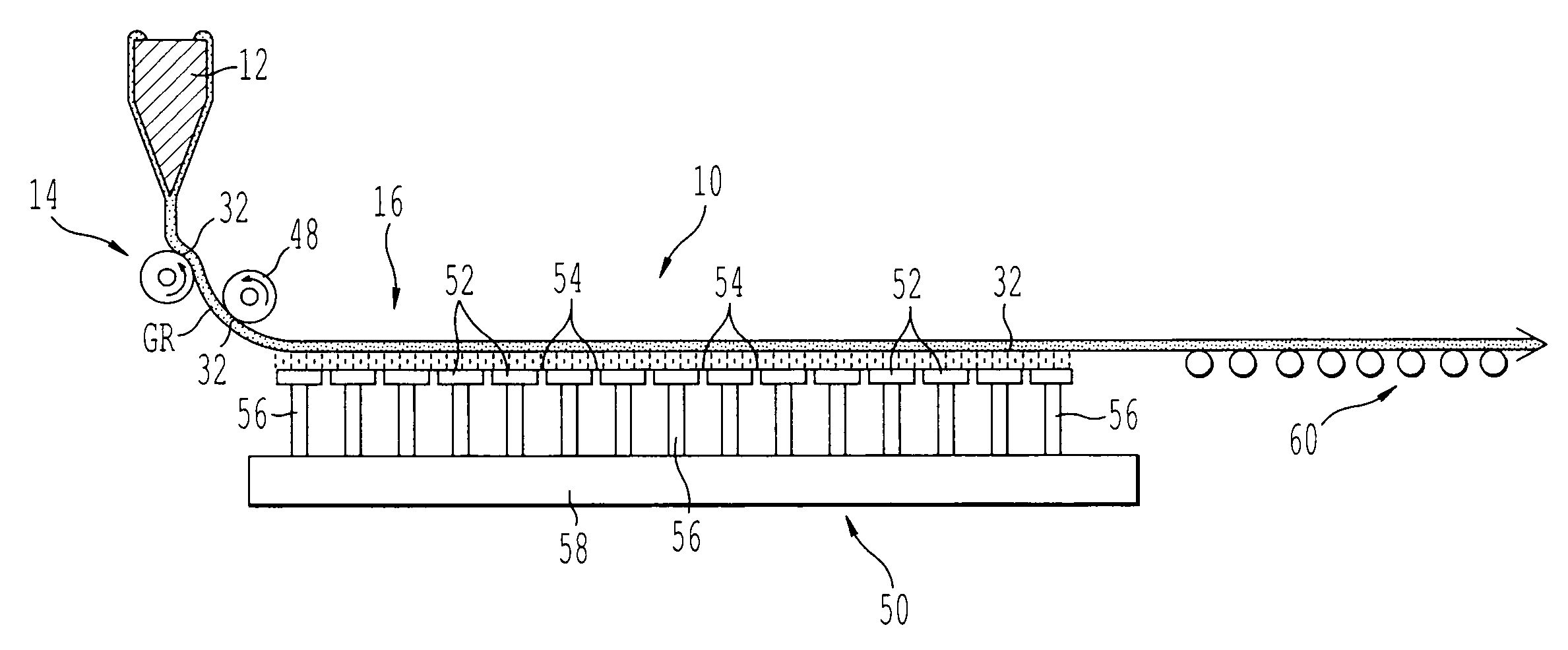
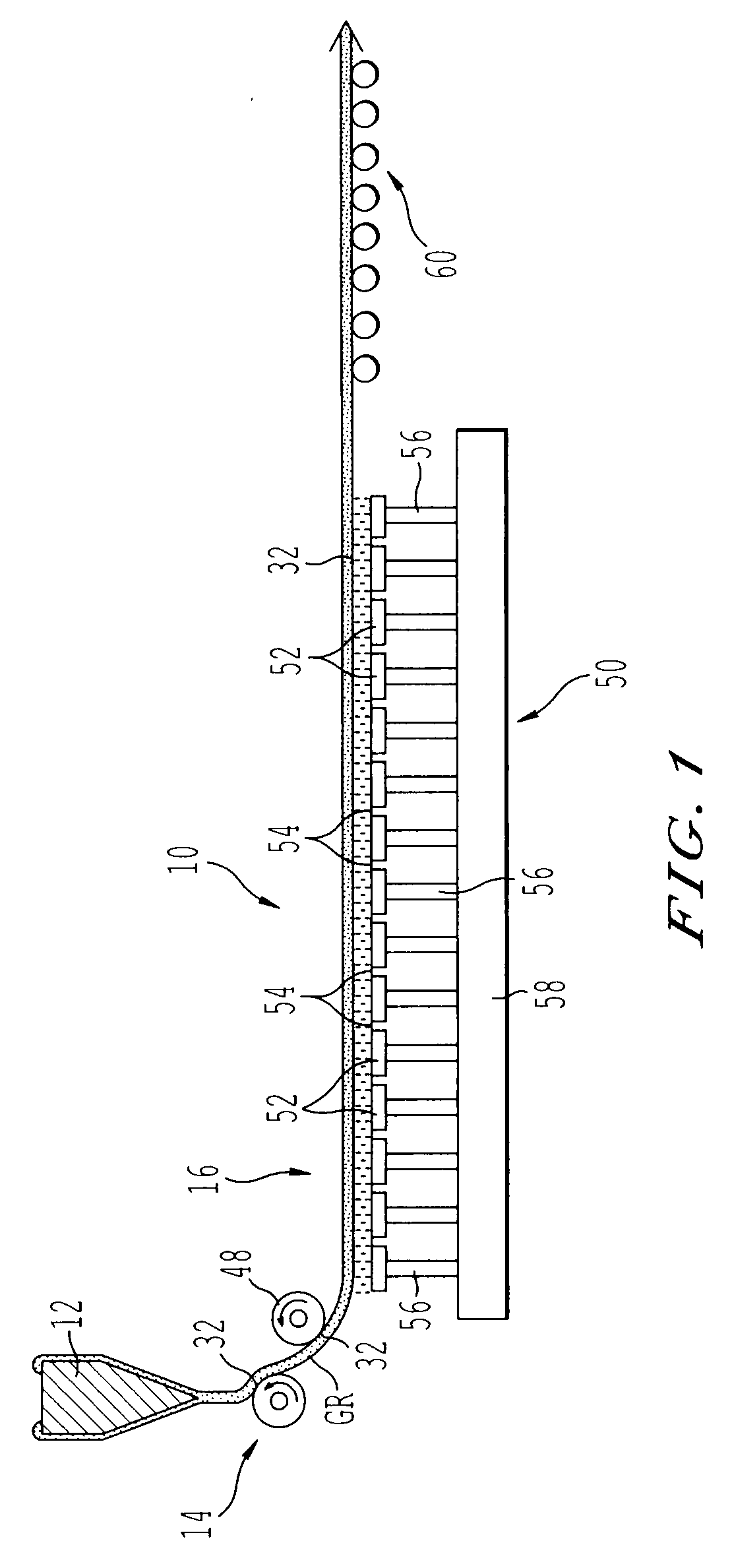
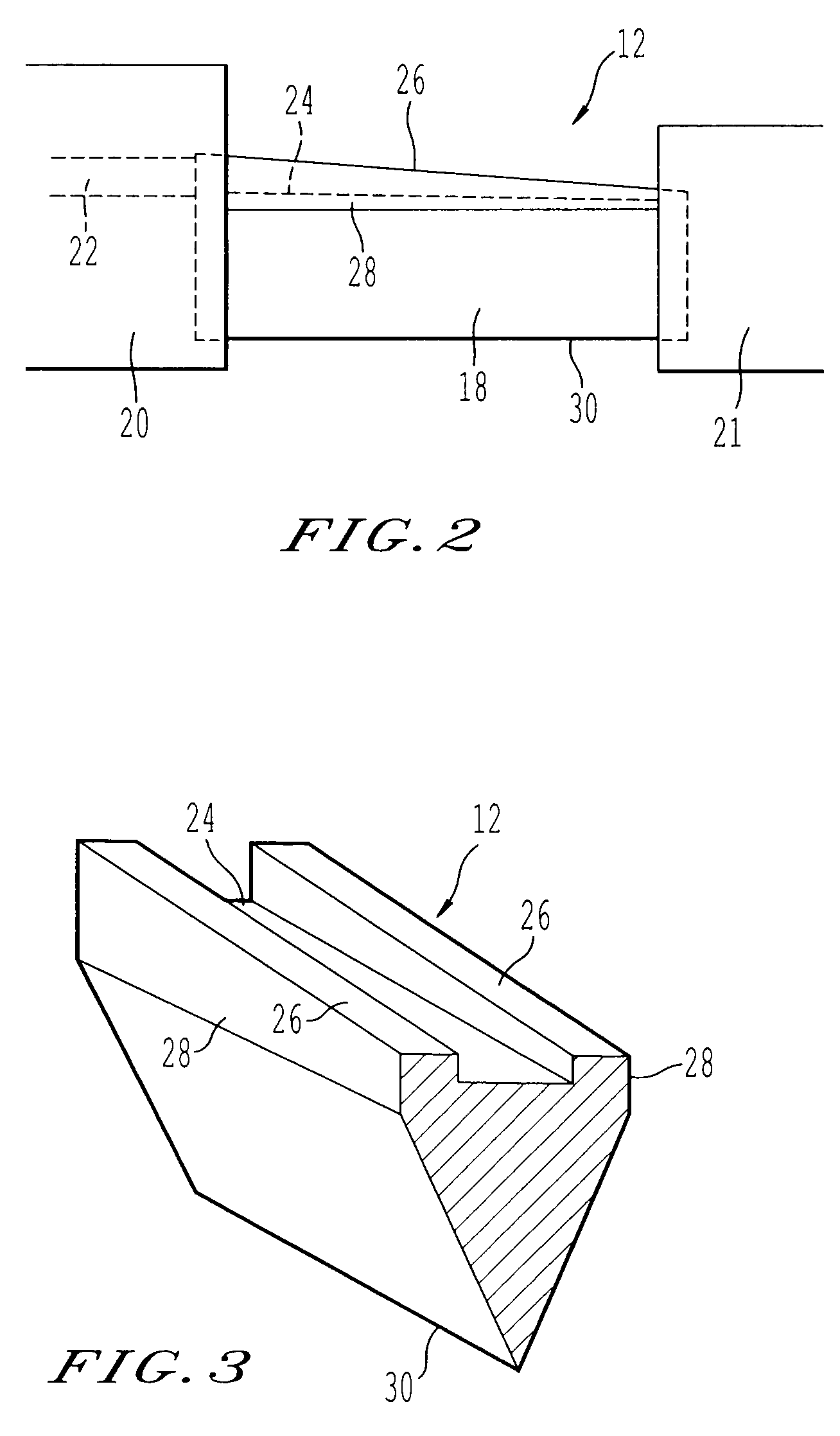
[0027]FIG. 1 is a schematic view of the entire structure of an apparatus for manufacturing thin sheet glass, according to the present invention, FIG. 2 is a front view of a forming body, and FIG. 3 is a cross-sectional view of the forming body.

[0028]The apparatus for manufacturing thin sheet glass 10, s according to the present invention comprises the forming body 12; a non-contact support member 14 for supporting a glass ribbon GR over the entire width in a non-contact state, the glass ribbon being pulled down from the forming body 12; and a horizontally pulling device 16 for horizontally pulling the downwardly pulled glass ribbon GR in a non-contact state.

[0029]As shown in FIG. 2 and FIG. 3, the forming body 12 comprises a main body 18 having a wedge-shaped form converging downwardly in secti...


PUM

PropertyMeasurementUnit
viscosityaaaaaaaaaa
viscosityaaaaaaaaaa
viscosityaaaaaaaaaa

Abstract

In an apparatus for manufacturing thin sheet glass, comprising a forming body 12 including a main body having a cross-sectional shape converging downwardly, the main body being configured to converging streams of molten glass into a single glass ribbon at a lower converged edge portion thereof, the streams of the molten glass flowing down along both surface of the main body; and edge members, the edge members being configured to restrict a width of the molten glass, wherein the glass ribbon formed by the forming body 12 is downwardly pulled to form thin sheet glass; the apparatus further includes a non-contact support member disposed in the vicinity of the lower converged edge portion of the main body, the non-contact support member being configured to form a thin gas layer on a supporting surface thereof, wherein the glass ribbon is supported over an entire width thereof in a non-contact way by the non-contact support member in a course wherein the glass ribbon is downwardly pulled.

Description

[0001]This application is a continuation of U.S. application Ser. No. 11 / 030,294, filed Jan. 7, 2005 which is a continuation of PCT / JP03 / 08531, filed Jul. 4, 2003, which claims the benefit of Japanese Patent Application No. 2002-198946 filed on Jul. 8, 2002 including specification, claims, drawings and summary is incorporated herein by reference in its entirety.BACKGROUND OF THE INVENTION[0002]1. Technical Field[0003]The present invention relates to an apparatus for manufacturing sheet glass, in particular an apparatus for manufacturing glass into a thin sheet, the glass having a high devitrification temperature.[0004]2. Background Art[0005]As a process for manufacturing thin sheet glass having high quality, there has been known a process called an overflow fusion process.[0006]The overflow fusion process is a process wherein a glass ribbon is formed by converging streams of molten glass just under a lower converged edge portion of a forming body having a wedge-shaped form convergin...

Claims


Application Information

Patent Timeline
Patent Type & Authority Applications(United States)
IPC IPC(8): C03B17/06C03B35/24C03B40/02
CPCC03B17/062C03B35/188C03B35/246C03B17/064
Inventor SHIRAISHI, YOSHIHIROSAKAMOTO, OSAMU
Owner ASAHI GLASS CO LTD
Why Eureka
Try Eureka