Methods of forming graphene liners and/or cap layers on copper-based conductive structures

a technology of conductive structure and graphene, which is applied in the manufacture of semiconductor/solid-state devices, electrical equipment, solid-state devices, etc., can solve the problems of limited size of conductive contact elements and structures, difficult etching of copper-based materials, and difficulty in using low-k dielectric materials

Inactive Publication Date: 2014-05-29
GLOBALFOUNDRIES INC
View PDF5 Cites 267 Cited by
  • Summary
  • Abstract
  • Description
  • Claims
  • Application Information

AI Technical Summary

Benefits of technology

[0010]The following presents a simplified summary of the invention in order to provide a basic understanding of some aspects of the invention. This summary is not an exhaustive overview of the invention. It is not intended to identify key or critical elements of the invention or to delineate the scope of the invention. Its sole purpose is to present some concepts in a simplified form as a prelude to the more detailed description that is discussed later.

Problems solved by technology

However, there are certain problems that arise with the ongoing shrinkage of feature sizes that may at least partially offset the advantages obtained by such feature size reduction.
This scaling also limits the size of the conductive contact elements and structures, which has the effect of increasing their electrical resistance.
However, the use of such low-k dielectric materials can be problematic as they tend to be less resistant to metal migration as compared to some other dielectric materials.
Copper is a material that is difficult to etch using traditional masking and etching techniques.
Unfortunately, it is becoming more difficult to satisfy the ongoing demand for smaller and smaller conductive lines and conductive vias for a variety of reasons.
One such problem with traditional barrier layer materials, e.g., tantalum, tantalum nitride, ruthenium, is the minimum thickness to which those materials must be formed so that they can be formed as continuous layers and perform their intended functions.
Efforts to form the barrier layers to ever decreasing thicknesses runs the risk that the barrier layers will not be formed as continuous films and that they will, therefore, not be able to perform at least some of their intended functions, e.g., they may not be able to effectively prevent migration of copper into unwanted areas, and the barrier layer may be incapable of serving, if need be, as a shunt in the case where the copper structure has degraded due to electromigration.

Method used


Image

  • Methods of forming graphene liners and/or cap layers on copper-based conductive structures
  • Methods of forming graphene liners and/or cap layers on copper-based conductive structures
  • Methods of forming graphene liners and/or cap layers on copper-based conductive structures

Examples


Embodiment Construction

[0017]Various illustrative embodiments of the invention are described below. In the interest of clarity, not all features of an actual implementation are described in this specification. It will of course be appreciated that in the development of any such actual embodiment, numerous implementation-specific decisions must be made to achieve the developers' specific goals, such as compliance with system-related and business-related constraints, which will vary from one implementation to another. Moreover, it will be appreciated that such a development effort might be complex and time-consuming, but would nevertheless be a routine undertaking for those of ordinary skill in the art having the benefit of this disclosure.

[0018]The present subject matter will now be described with reference to the attached figures. Various structures, systems and devices are schematically depicted in the drawings for purposes of explanation only and so as to not obscure the present disclosure with details ...


PUM

PropertyMeasurementUnit
temperatureaaaaaaaaaa
thicknessaaaaaaaaaa

Abstract

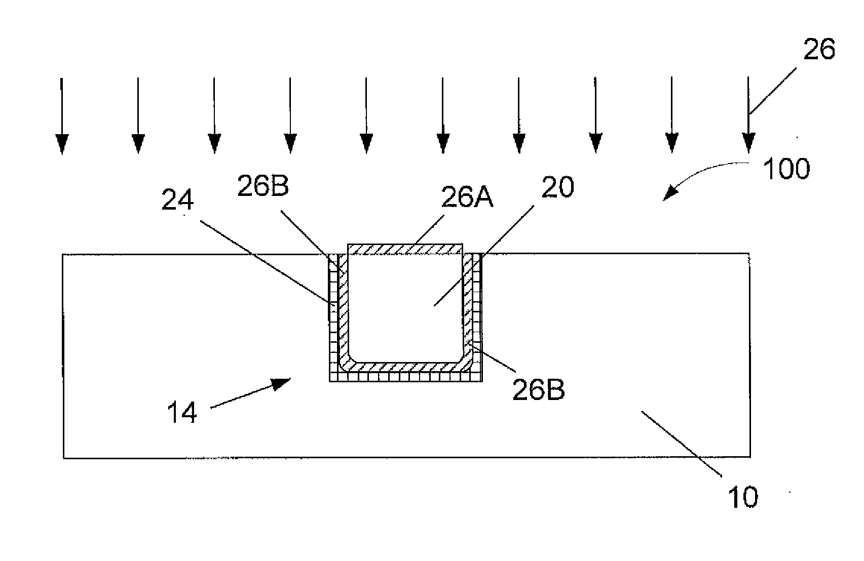
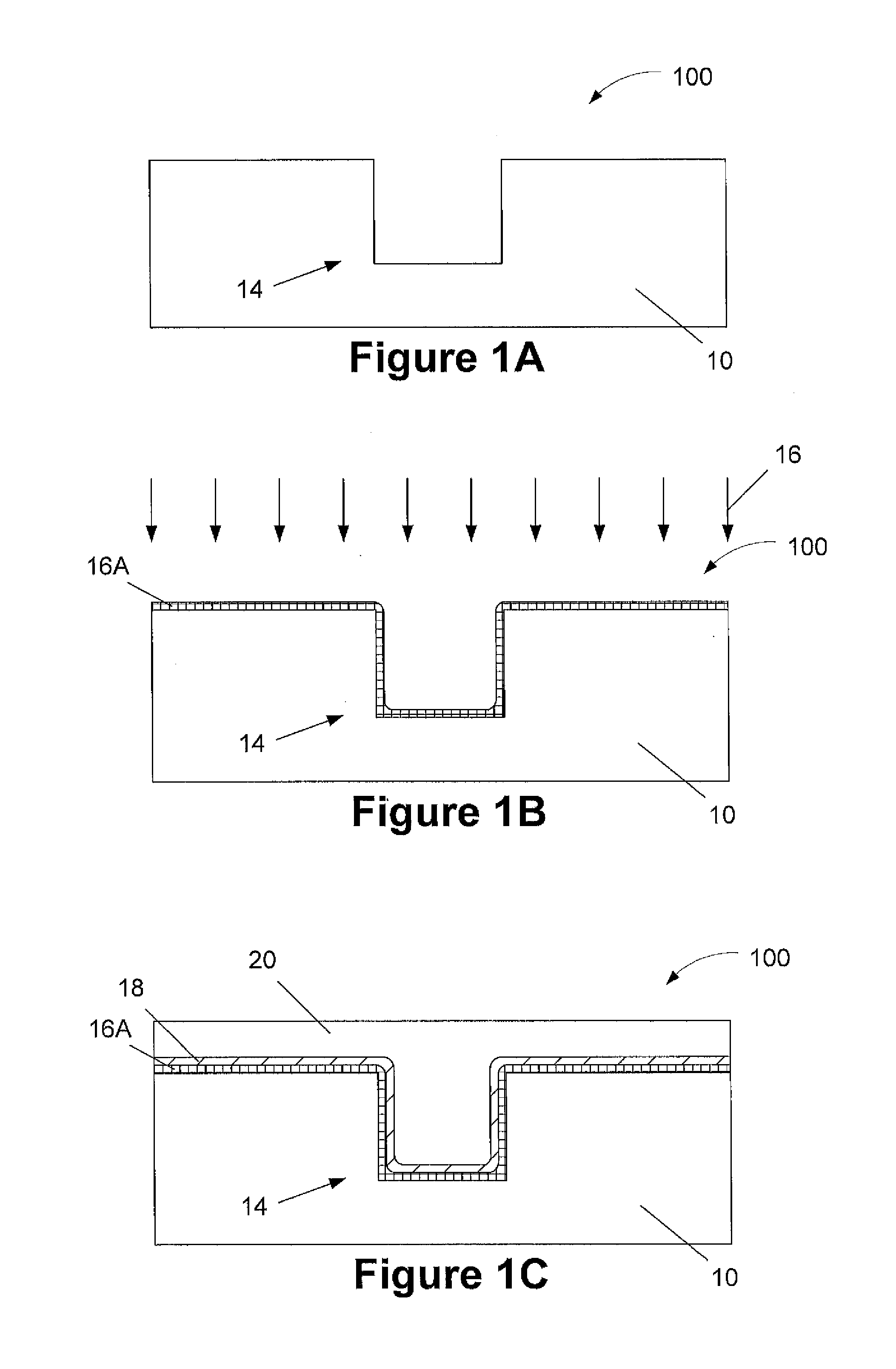
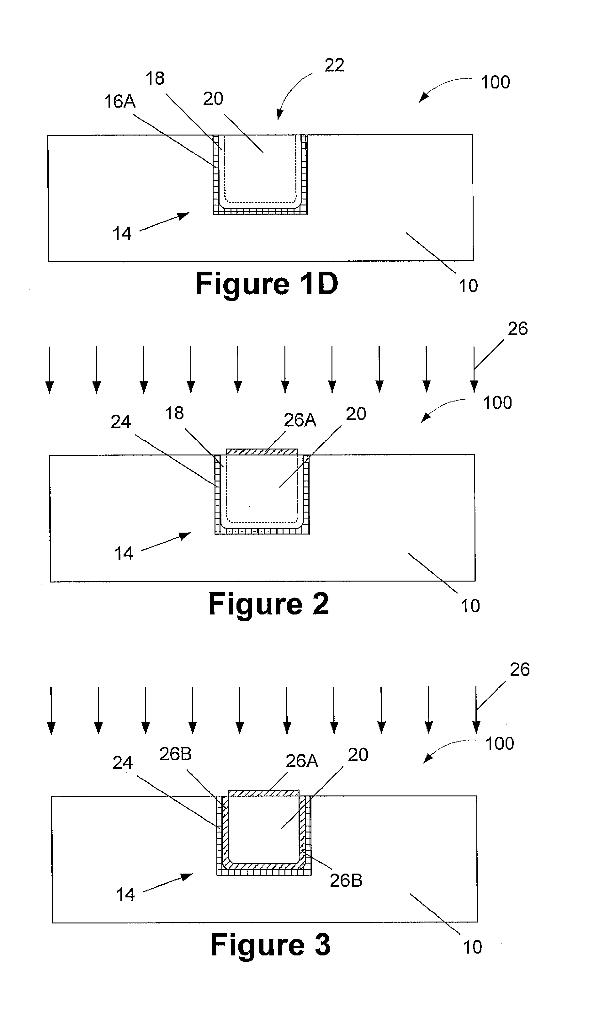
One illustrative method disclosed herein includes forming a trench/via in a layer of insulating material, forming a graphene liner layer in at least the trench/via, forming a copper-based seed layer on the graphene liner layer, depositing a bulk copper-based material on the copper-based seed layer so as to overfill the trench/via, and performing at least one chemical mechanical polishing process to remove at least excess amounts of the bulk copper-based material and the copper-based seed layer positioned outside of the trench/via to thereby define a copper-based conductive structure with a graphene liner layer positioned between the copper-based conductive structure and the layer of insulating material.

Description

BACKGROUND OF THE INVENTION [0001]1. Field of the Invention[0002]Generally, the present disclosure relates to the manufacture of sophisticated semiconductor devices, and, more specifically, to various methods of forming graphene liners and / or capping layers on copper-based conductive structures.[0003]2. Description of the Related Art[0004]The fabrication of advanced integrated circuits, such as CPUs, storage devices, ASICs (application specific integrated circuits) and the like, requires a large number of circuit elements, such as transistors, capacitors, resistors, etc., to be formed on a given chip area according to a specified circuit layout. During the fabrication of complex integrated circuits using, for instance, MOS (Metal-Oxide-Semiconductor) technology, millions of transistors, e.g., N-channel transistors (NFETs) and / or P-channel transistors (PFETs), are formed on a substrate including a crystalline semiconductor layer. A field effect transistor, irrespective of whether an ...

Claims


Application Information

Patent Timeline
Patent Type & Authority Applications(United States)
IPC IPC(8): H01L21/768H01L23/48
CPCH01L23/481H01L21/76843H01L21/76849H01L21/76867H01L23/53238H01L2924/0002H01L2924/00
Inventor RYAN, ERROL T.KRIVOKAPIC, ZORANZHANG, XUNYUANWITT, CHRISTIANHE, MINGZHAO, LARRY
Owner GLOBALFOUNDRIES INC
Why Eureka
Try Eureka