Driving force transmitting device for four-wheel drive vehicle

a transmission device and four-wheel drive technology, applied in mechanical actuated clutches, road transportation, gearing, etc., can solve the problems of reducing the mileage of the running side, affecting the performance of the driving side, and the clutch discs of the driving side being unable to contact, so as to reduce the oil viscosity resistance and friction loss, not deteriorate the mileage

Inactive Publication Date: 2009-08-27
UNIVANCE CORP
View PDF7 Cites 20 Cited by
  • Summary
  • Abstract
  • Description
  • Claims
  • Application Information

AI Technical Summary

Benefits of technology

[0007]According to the present invention to provide a driving force transmission device for four-wheel-drive vehicle which is based on the two-wheel drive of rear wheels, and does not-sacrifice the change response from the two-wheel drive to t

Problems solved by technology

However, there is a fear that the multi-disc clutch mechanism 310 may be seized if sufficient lubrication is not performed at the time of the driving force distribution control.
Furthermore, as a method to ensure sufficient intervals among the respective clutch discs in the released state of the multi-disc clutch mechanism 310, a method is suggested in which a ring spring 332 formed in a wave shape in the circumferential direction as shown in FIG. 2 is put between adjacent clutch discs of the driving side, or adjacent clutch discs of the driven side, however, according to this method, it is possible to ensure the sufficient intervals between the clutch discs of the driving side or the clutch discs of the driven side, but

Method used


Image

  • Driving force transmitting device for four-wheel drive vehicle
  • Driving force transmitting device for four-wheel drive vehicle
  • Driving force transmitting device for four-wheel drive vehicle

Examples


Embodiment Construction

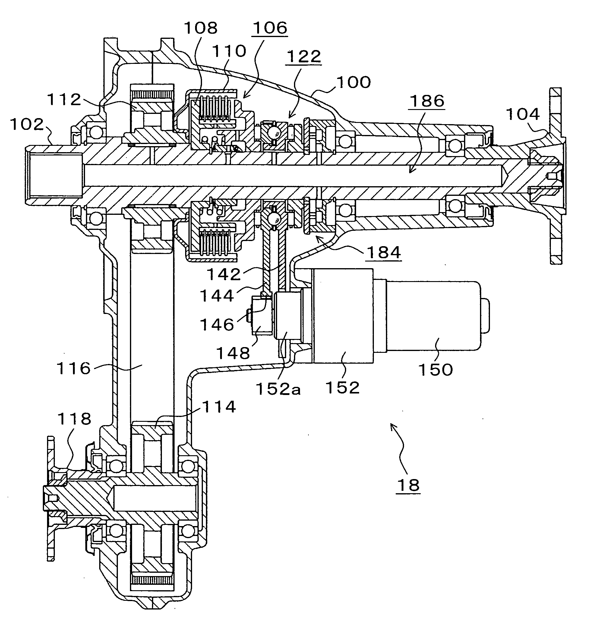
[0044]FIG. 3 is an explanatory diagram showing an embodiment of a driving force transmission device for four-wheel-drive vehicle based on the two-wheel drive of rear wheels according to the present invention, and shows a case the device is applied to a vehicle in which rear wheels are driven in the two-wheel-drive mode. In FIG. 4, a driving force transmission device 10 according to the present embodiment is provided in a four-wheel drive vehicle 12, and includes a driving force distribution device 18, a rear wheel differential 20 and a front wheel differential 22. The rear wheel differential 20 and the front wheel differential 22 are connected with the driving force distribution device 18 through a rear wheel propeller shaft 24 and a front wheel propeller shaft 26 respectively. The driving force from an engine 14 is changed by a gearbox 16, and input into an input shaft 102 of the driving force distribution device 18, and in the two-wheel-drive mode, when a multi-disc clutch mechani...


PUM


Abstract

A driving force transmission device for four-wheel-drive vehicle based on the two-wheel drive of rear wheels or front wheels is provided. In the case of the two-wheel drive of rear wheels, a multi-disc clutch mechanism for controlling the driving force distribution to a front wheel output shaft, and a disconnection/connection mechanism for disconnecting and connecting a front wheel differential and a left front wheel drive shaft are provided, and in the two-wheel drive of rear wheels, the dragging torque of the multi-disc clutch mechanism is made smaller than the friction torque of a front wheel driving force transmission section, and the front wheel differential and the left front wheel drive shaft are disconnected by the disconnection/connection mechanism, thereby the rotation of the front wheel driving force transmission section is stopped.

Description

[0001]This application is a priority based on prior application No. JP 2008-42409, filed February 25, in Japan.BACKGROUND OF THE INVENTION[0002]1. Field of the Invention[0003]The present invention relates to a driving force transmission device for four-wheel-drive vehicle based on the two-wheel drive of rear wheels enabling to change a two-wheel drive and a four-wheel drive, more specifically, to a driving force transmission device for four-wheel-drive vehicle in which the rotation of the parts not operative for the transmission of the driving force in the two-wheel drive is stopped.[0004]2. Description of the Related Arts[0005]As one of driving force transmission devices for four-wheel-drive vehicle in which rear wheels are driven in the two-wheel drive, and the distribution control of the driving force to the front wheels is performed in the four-wheel drive by a multi-disc clutch mechanism, in the four-wheel-drive vehicle based on the two-wheel drive of conventional so-called on-...

Claims


Application Information

Patent Timeline
IPC IPC(8): B60K17/35
CPCB60K23/08F16D13/69F16D13/72F16D27/004Y02T10/76F16D28/00F16D2023/123F16D2048/0221F16D27/115F16H13/14F16D13/74F16D13/52
Inventor KATO, TADAHIKOSUZUKI, SATORU
Owner UNIVANCE CORP
Why Eureka
Try Eureka