Filtration method, filter-incorporated tip, and filtration device

a technology of filtration method and filter, which is applied in the direction of filtration separation, separation process, laboratory glassware, etc., can solve the problems of only being able to control the centrifuge, increasing the overall size of the equipment, and difficult to automate a series of operations including preprocessing, so as to reduce the number of parts and therefore the manufacturing cost, reliably lock the filter, and easy to lock the

Active Publication Date: 2009-12-03
UNIVERSAL BIO RESEARCH CO LTD
View PDF39 Cites 34 Cited by
  • Summary
  • Abstract
  • Description
  • Claims
  • Application Information

AI Technical Summary

Benefits of technology

[0074]In the ninth aspect of the invention, the filter support members are provided separate from the nozzle-tipped container. Thus, by installing the filter support members in the nozzle-tipped container, the filter can easily be locked. Further, by removably installing the filter support members, the tip member can be reused and the substance separated by the filter can be directly extracted or collected.
[0075]In the tenth aspect of the invention, the filter locking portion is provided in the form of an inwardly protruding portion bulging from the inner wall surface of the nozzle-tipped container, in the form of an inclined surface or in the form of a step. This construction reduces the parts count and therefore the manufacturing cost and makes it possible to reliably lock the filter.
[0076]The filter or filter support members are locked and securely held by the protruding portion, the inclined surface or the step. Therefore, the locking of the filter in the nozzle-tipped container is secure and reliable.
[0077]Particularly by using the step and the inclined surface of the transition portion rangin

Problems solved by technology

The use of a centrifuge that is required in performing filtration using a filter through which a liquid cannot easily pass has a problem of expanding the overall size of the equipment.
There is another problem that installing the sample holding container assemblies in the centrifuge can only be done manually, making it difficult to automate a series

Method used


Image

  • Filtration method, filter-incorporated tip, and filtration device
  • Filtration method, filter-incorporated tip, and filtration device
  • Filtration method, filter-incorporated tip, and filtration device

Examples


first embodiment

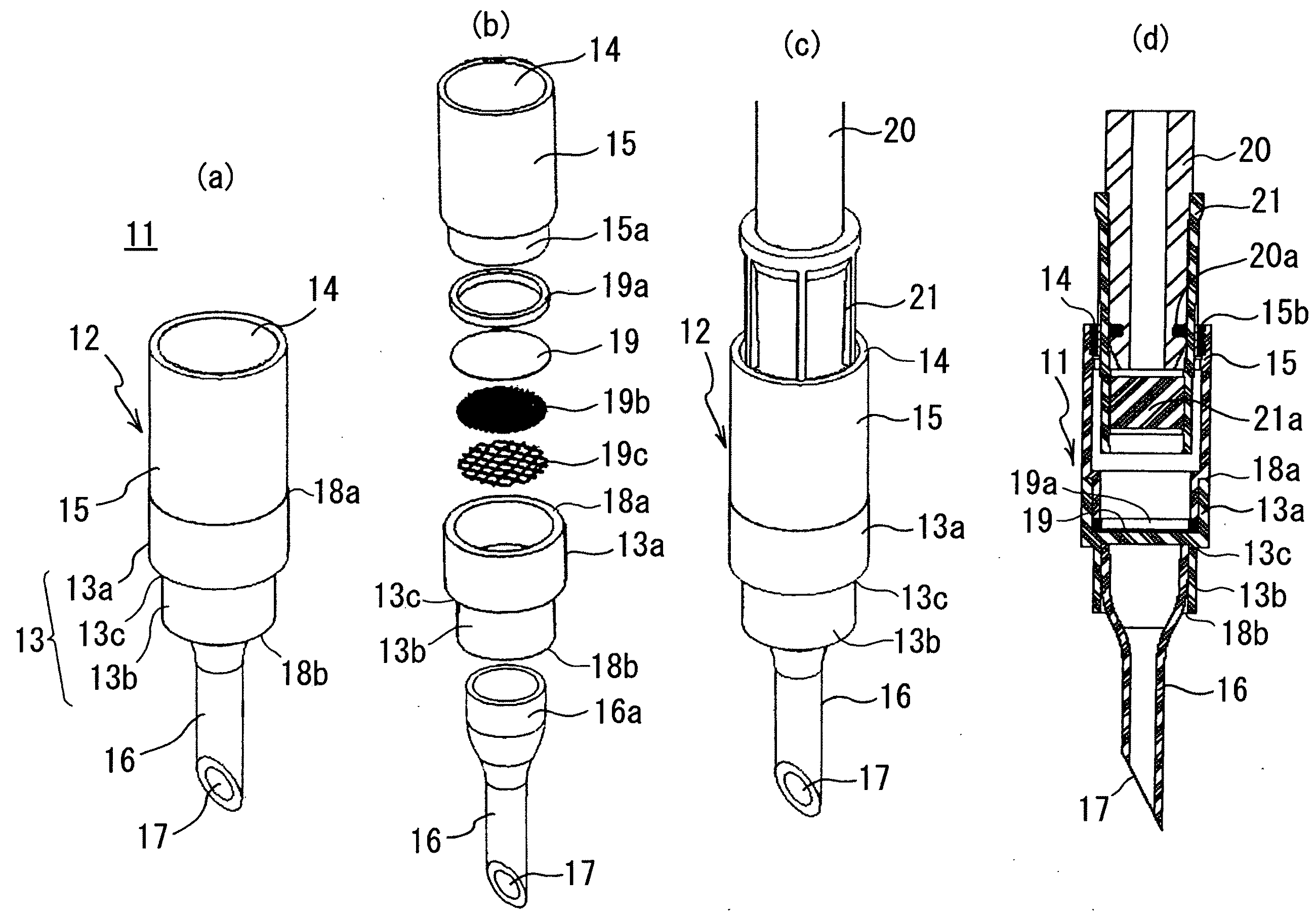
[0093]FIG. 1(a) shows an external view of a filter-incorporated tip according to this invention.

[0094]The filter-incorporated tip 11 has a nozzle-tipped container 12 incorporating a thin-film filter 19 to be described later. The nozzle-tipped container 12 comprises a guide tube 15 with a large diameter of a few millimeters to several tens of millimeters, preferably a few millimeters to ten-odd millimeters, a narrow tube 16 formed narrower than the guide tube 15, and a transition portion 13 provided between the guide tube 15 and the narrow tube 16. Here, the narrow tube 16 and the transition portion 13 correspond to the filter locking tube. These components are separable at an opening portion 18a between the guide tube 15 and the transition portion 13 and also at an opening portion 18b between the transition portion 13 and the narrow tube 16. On the upper side of the guide tube 15 is provided a guide opening portion 14. At a lower end of the narrow tube 16 is provided a front nozzle ...

second embodiment

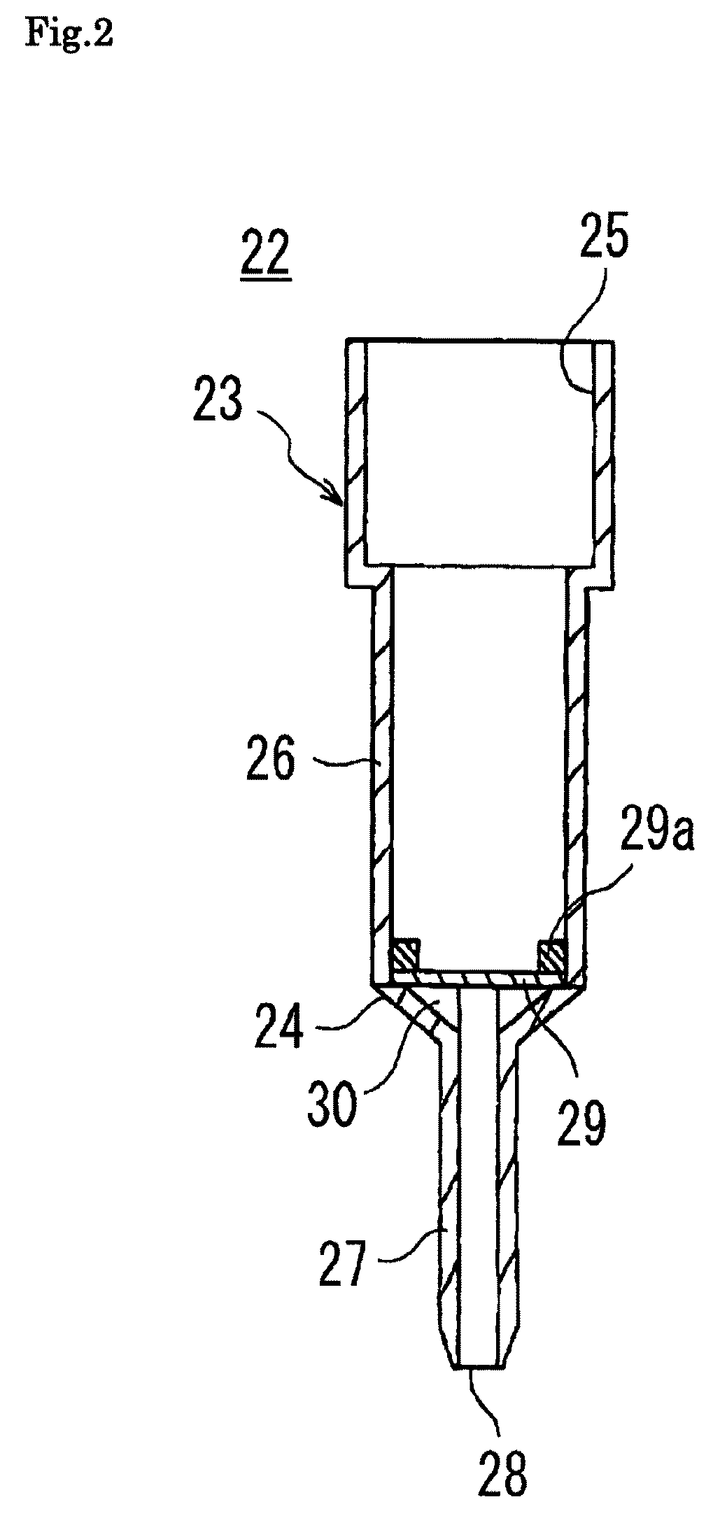
[0102]FIG. 2 shows a filter-incorporated tip 22 according to this invention.

[0103]The filter-incorporated tip 22 has a nozzle-tipped container 23 and a thin-plate filter 29 described later which is locked inside.

[0104]The nozzle-tipped container 23 has a large-diameter tube 26, a small-diameter tube 27 communicating with and formed narrower than the large-diameter tube 26, and a transition portion 24 provided between the large-diameter tube 26 and the small-diameter tube 27. In this embodiment, unlike the first embodiment, the large-diameter tube 26, the transition portion 24 and the small-diameter tube 27 are not separable. On the top of the large-diameter tube 26 is provided a guide opening portion 25. At a lower end of the small-diameter tube 27 is provided a front nozzle portion 28. The transition portion 24 is generally conical, when viewed from outside, and installed coaxial with the small-diameter tube 27. It has a plurality of right triangular support plates 30 radially exte...

third embodiment

[0108]FIG. 3 shows a filter-incorporated tip 32 according to a

[0109]As shown in FIG. 3(a) and FIG. 3(b) which is a cross-sectional view taken along the line AA of FIG. 3(a), the filter-incorporated tip 32 has a cylindrical, permeable, porous block filter 43 held in a nozzle-tipped container 33.

[0110]The nozzle-tipped container 33 has a roughly cylindrical large-diameter tube 35, a small-diameter tube 37 communicating with and formed narrower than the large-diameter tube 35, a filter accommodating tube 36a capable of accommodating the block filter 43 with a diameter intermediate between those of the large-diameter tube 35 and the small-diameter tube 37, and a transition portion 36 having a step 40 formed between it and the large-diameter tube 35 and a step 39 formed between it and the small-diameter tube 37. The inner diameter and depth of the filter accommodating tube 36a of the transition portion 36 are almost equal to the outer diameter and height of the block filter 43 so that th...


PUM

PropertyMeasurementUnit
Pressureaaaaaaaaaa
Diameteraaaaaaaaaa

Abstract

The present invention relates to a filtration method, a filter-incorporated tip and a filtration device, and its object is to perform efficient and swift isolation of a target substance. The filtration method therefore comprises: a liquid introducing step to introduce a liquid into a filter-incorporated tip through a guide opening portion thereof, wherein the filter-incorporated tip has a nozzle-tipped container and a filter, the nozzle-tipped container has a guide opening portion that can be directly or indirectly fitted to an air nozzle capable of ejecting a gas and a front nozzle portion capable of delivering the liquid by the ejection of the gas from the air nozzle, and the filter is locked in the nozzle-tipped container to partition the interior of the nozzle-tipped container into the guide opening portion side and the front nozzle portion side and is adapted to temporarily hold the liquid and isolate a predetermined substance as the liquid passes through the filter, with the nozzle-tipped container coupled to the air nozzle on the guide opening portion side; a coupling step to directly or indirectly couple the filter-incorporated tip containing the liquid to the air nozzle; and a pressure application step to eject the gas from the air nozzle into the coupled filterincorporated tip.

Description

TECHNICAL FIELD[0001]The present invention relates to a filtration method, a filter-incorporated tip and a filtration device.BACKGROUND ART[0002]In separating or removing a certain substance from a liquid by using a filter that does not let the liquid pass easily therethrough, it is a common practice to use a centrifuge. To process a liquid by the centrifuge, a sample holding container has been in common use which is generally cylindrical and comprises a vial-engaging opening portion at a lower end thereof engageable with an opening portion of a filtered product accommodating glass vial, a sample-introducing opening portion at an upper end thereof into which a sample liquid to be filtered is introduced, a filter provided between the vial-engaging opening portion and the sample-introducing opening portion to separate them from each other, and a cover to hermetically close the sample-introducing opening portion.[0003]To filtrate a biological substance using the sample holding containe...

Claims


Application Information

Patent Timeline
IPC IPC(8): B01D37/00B01D29/00B01D29/88
CPCB01D61/145G01N2035/1053B01L2300/0681B01L3/0275
Inventor TAJIMA, HIDEJIHATANO, TOMOYUKIFUMOTO, MASATAKAKOH, YOSHINORISAEGUSA, TOMOMI
Owner UNIVERSAL BIO RESEARCH CO LTD
Why Eureka
Try Eureka