Balun

a technology of balun and insulating layer, applied in the field of balun, can solve the problems of poor electrical performance of balun b>100/b> and poor quality factor of balun, and achieve the effects of improving quality factor, reducing return loss and insertion loss, and small thickness

Active Publication Date: 2009-12-03
CYNTEC
View PDF6 Cites 3 Cited by
  • Summary
  • Abstract
  • Description
  • Claims
  • Application Information

AI Technical Summary

Benefits of technology

[0027]Because all of the first metallic layer, the second metallic layer, the third metallic layer, and the first dielectric layer are fabricated by thin film processing, each of the metallic layers does not demand for an independent dielectric substrate. As such, comparing with the conventional laminate, the balun according to the embodiments of the present invention has a smaller thickness and employing fewer layers. Further, within a certain frequency bandwidth, because each second distance is smaller than each first distance and each fourth distance is smaller than each third distance, the return loss and the insertion loss can be reduced while the unbalanced I / O serves as an input electrode and the first balanced I / O and the second balanced I / O serve as output electrodes. Further, the balun according to the embodiments of the present invention can achieve an improved quality factor Q. Briefly, comparing with the conventional balun, the balun according of the present invention has an improved electrical performance.

Problems solved by technology

Further, the conventional balun 100 has a poor quality factor Q. Briefly, the conventional balun 100 has a poor electrical performance.

Method used


Image

  • Balun
  • Balun
  • Balun

Examples


first embodiment

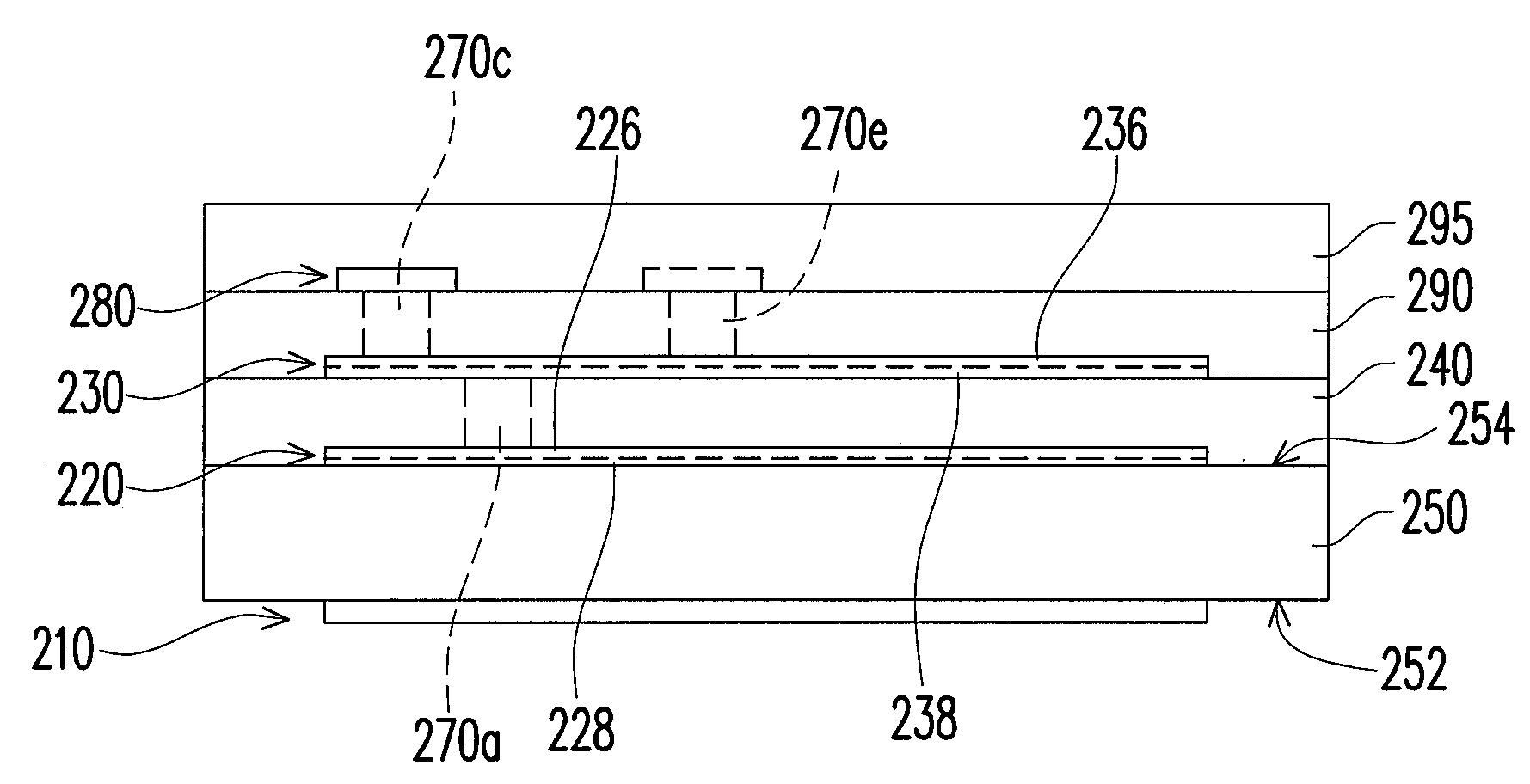
[0046]Referring to FIGS. 2A, 2B, 3, and 4A, a balun 200 according to a first embodiment of the present invention includes a first metallic layer 210, a second metallic layer 220, a third metallic layer 230, a first dielectric layer 240, a dielectric substrate 250, a plurality of external electrodes 260a, 260b, 260c, 260d, 260e, and 260f, a plurality of conductive channels 270a, 270b, 270c, 270d, 270e, and 270f (as shown in FIGS. 4D and 4F), a fourth metallic layer 280, a second dielectric layer 290, and a protective layer 295. The first metallic layer 210, the second metallic layer 220, the third metallic layer 230, the first dielectric layer 240, the fourth metallic layer 280, and the second dielectric layer 290 are fabricated by thin film processing and together with the dielectric substrate 250 entirely configure a body 20. The external electrodes 260a, 260b, 260c are disposed at a first side surface 22a of the body 20. The external electrodes 260d, 260e, 260f are disposed at a s...

second embodiment

[0064]Referring to FIGS. 10, 11C, and 11E, a balun 300 according to a second embodiment of the present invention is shown. The balun 300 differs from the balun 200 according to the first embodiment in that it is configured with different shape of spiral lines, and different electrical connecting positions between external electrodes and the unbalanced I / O end, the balanced I / O ends, and the open-circuit end. In other words, according to the current embodiment, the shapes of the spiral lines are modified because of the electrical connecting positions between external electrodes and the unbalanced I / O end, the balanced I / O ends, and the open-circuit end. Specifically, an outermost circle of a first spiral line 322 of a second metallic layer 320 defines a fifth region A5′, and an outermost circle of a second spiral line 324 of the second metal layer 320 defines a sixth region A6′. An outermost circle of a third spiral line 332 of a third metallic layer 330 defines a seventh region A7′,...


PUM


Abstract

A balun includes a first, second, and third metallic layers, a first dielectric layer disposed between the second and third metallic layers, and a dielectric substrate. The second metallic layer includes a first spiral line having sequentially connected first line segments and a second spiral line having sequentially connected second line segments. A first distance between each two opposite sides of a first region encircled by the innermost first line segments is greater than a second distance between each two adjacent parallel first line segments. A third distance between each two opposite sides of a second region encircled by the innermost second line segments is greater than a fourth distance between each two adjacent parallel second line segments. The third metallic layer includes a third and a fourth spiral lines. The first metallic layer and other elements as a whole are disposed on an opposite surface of the dielectric substrate.

Description

CROSS-REFERENCE TO RELATED APPLICATION[0001]This application claims the priority benefit of Taiwan application serial no. 97119950, filed May 29, 2008. The entirety of the above-mentioned patent application is hereby incorporated by reference herein and made a part of this specification.BACKGROUND OF THE INVENTION[0002]1. Field of the Invention[0003]The present invention generally relates to a balun, and more particularly, to a balun including a plurality of metallic layers.[0004]2. Description of Related Art[0005]A balun (balanced-unbalanced transformer) is a device for transforming a balanced signal to an unbalanced signal or transforming an unbalanced signal to a balanced signal. The balanced signal is made up of two signals that are nearly 180 degrees out of phase with each other and have nearly equal amplitudes. The balun usually has two balanced terminals for receiving and outputting balanced signals and one unbalanced terminal for receiving and outputting unbalanced signals.[...

Claims


Application Information

Patent Timeline
Patent Type & Authority Applications(United States)
IPC IPC(8): H01P5/10
CPCH01P5/10
Inventor LIU, CHING-HUNGLIU, CHEN-CHUNGWANG, KENG-HONG
Owner CYNTEC
Why Eureka
Try Eureka