Electric abrasive sharpener

a technology of electric abrasives and sharpeners, which is applied in the field of electric powered abrasive sharpeners, can solve the problems of reducing the sharpening efficiency of electric abrasives, so as to achieve the effect of reducing the blade kickback, reducing the cost of electric abrasives, and reducing the risk o

Active Publication Date: 2009-12-03
SMITHS CONSUMER PROD
View PDF12 Cites 1 Cited by
  • Summary
  • Abstract
  • Description
  • Claims
  • Application Information

AI Technical Summary

Benefits of technology

[0004]It is therefore an objective of the invention to provide an improved electric sharpener for knives, scissors, and other implements. The sharpener herein employs counter-rotating abrasive wheels with raised interconnecting abrasive threads that have a lead in and lead out chamfer to eliminate the kick back of the blade when being sharpen. The presence of the chamfers allows the grinding wheels to be flat to create a greater sharpening surface that is exposed on the wheel as compared to convex surfaces on wheels in the prior art. The unique drive train of the invention has an improved array of gears and belts that in conjunction with the sizing of the abrasive wheels allows the sharpener disclosed herein to employs a highly economical motor, while generating sufficiently high torque to the abrasive wheels for efficient sharpening. Although the electric sharpener herein is described in relation to four abrasive wheels forming two sharpening slots, the invention may be provided in accordance with teachings described as having a pair of counter rotating wheels forming one sharpening slot or more than two pairs of rotating abrasive wheels, if desired. Regardless of the number pairs of abrasive wheels employed, the pairs of wheels are respectively interconnected with a nesting design allowing for smaller wheels than compared to the prior art.

Problems solved by technology

Although some past designs produce satisfactory results, the self-powered systems in the prior art are relatively expensive and must rely on the use of heavy duty electric motors for attaining adequate torque to satisfactorily drive the abrasive wheels.
Another problem associated with known electric sharpeners is the danger and inconvenience to the user experiencing kick back of the blade being sharpened.
In addition, prior designs of electric sharpeners do not provide an optimum sharpening surface on the abrasive wheels for best results.

Method used


Image

  • Electric abrasive sharpener
  • Electric abrasive sharpener
  • Electric abrasive sharpener

Examples


Embodiment Construction

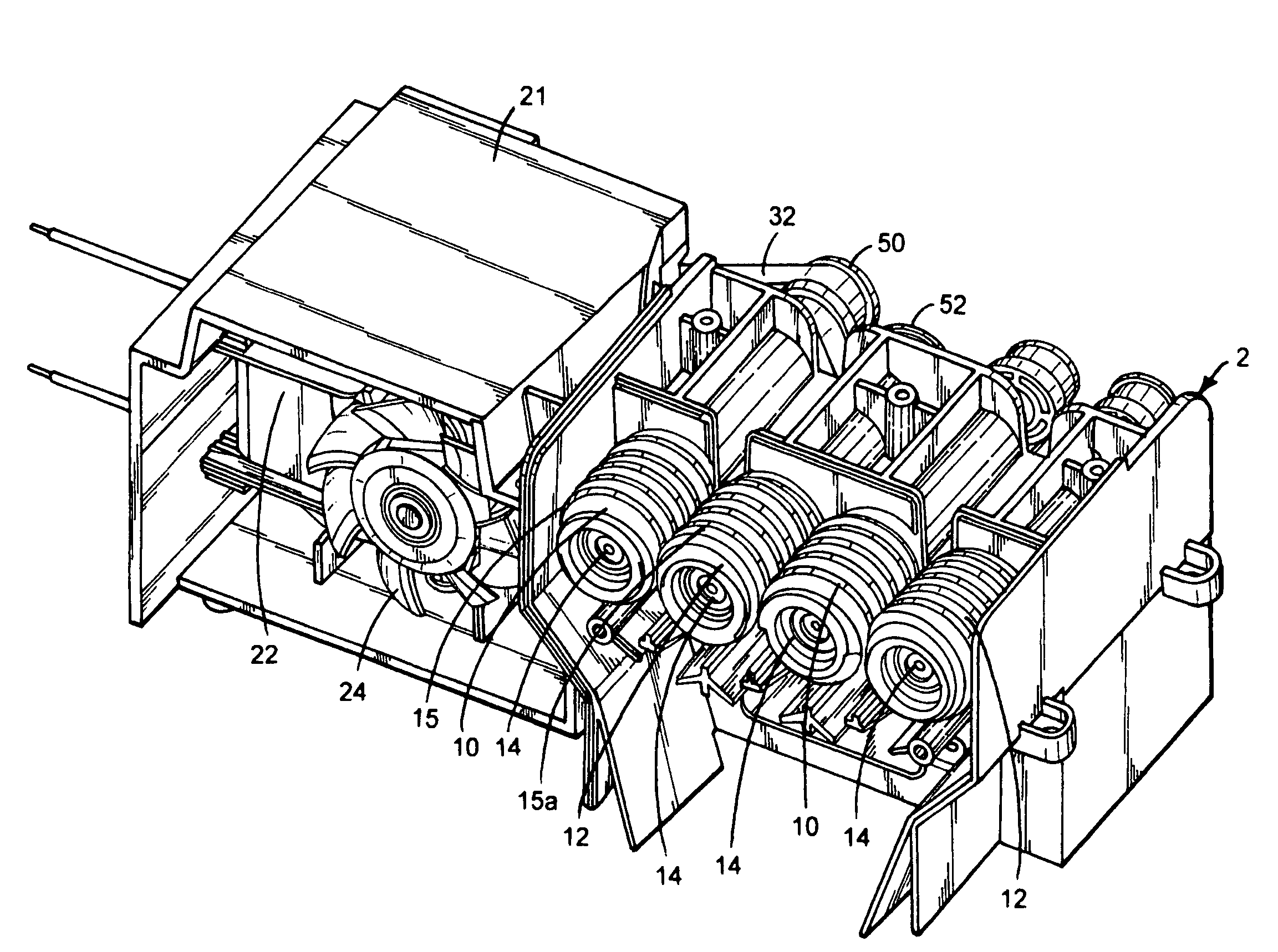
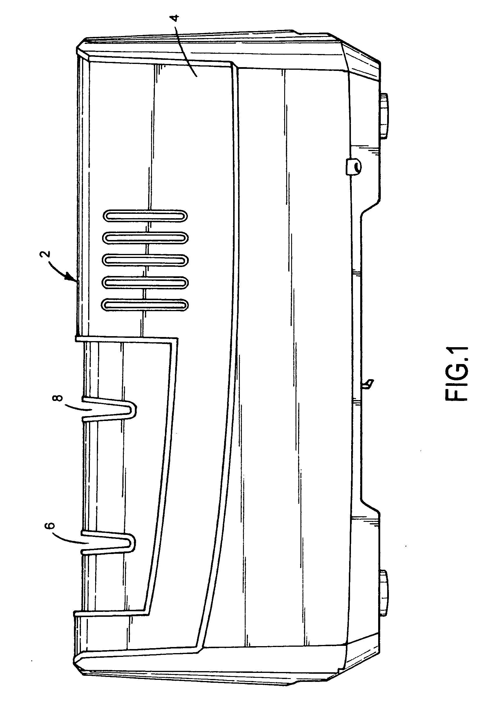
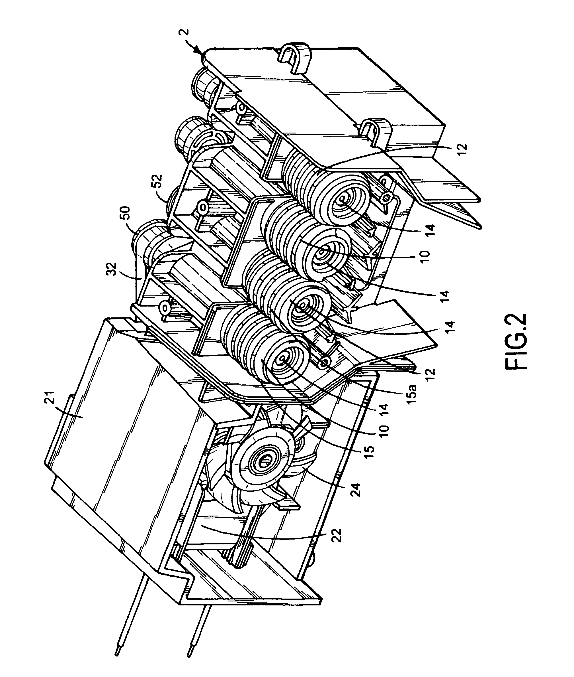
[0012]Referring now to FIGS. 1-7, there is illustrated the electric sharpener of the invention, generally designated by reference numeral 2. The sharpener 2 has a hollow housing 4 made of metal or plastic and the like. For purposes of manufacture, a combination of plastic and metal may be used effectively used to form housing 4. The housing 4 includes a pair of V-shaped slots 6 and 8 in which a pair of counter-rotating abrasive wheels 10 and 12, having a diamond abrasive or other suitable material is respectively mounted in sharpening slots 6 and 8. The wheels 10 and 12 have a central hub 14 respectively having integral helical ridges 15 and 15a in the form of raised continuous threads of generally the same radius from hub 14 as illustrated in FIGS. 5, 6, and 7. The ridges 15 and 15a overlap a portion of each other, whereby, for example, ridges 15 form right handed threads and ridges 15a form left handed threads. An abrasive material is affixed to outer peripheral surfaces 16 of the...


PUM

PropertyMeasurementUnit
lengthaaaaaaaaaa
radiusaaaaaaaaaa
torqueaaaaaaaaaa

Abstract

An electric abrasive sharpener for sharpening edges having pairs of interlocking abrasive wheels formed with opposite abrasive helical threads. Each end of the threads respectively has lead-in section and lead-out section having chamfer edge portion to eliminate kickback. The abrasive wheels of the sharpener is driven by a single phase AC motor connected to a motor drive that steps down the rotational speed of the output shaft of the motor to rotate the abrasive wheels with increased torque.

Description

BACKGROUND OF THE INVENTION[0001]This application claims priority to provisional application, Ser. No. 61 / 069,489 filed Mar. 14, 2008.FIELD OF THE INVENTION[0002]This invention relates to abrasive sharpeners, and more particularly, to an electric powered abrasive sharpener having counter-rotating wheels.SUMMARY OF THE PRIOR ART[0003]Numerous self-powered, electric abrasive sharpeners have been developed in the past. Although some past designs produce satisfactory results, the self-powered systems in the prior art are relatively expensive and must rely on the use of heavy duty electric motors for attaining adequate torque to satisfactorily drive the abrasive wheels. Another problem associated with known electric sharpeners is the danger and inconvenience to the user experiencing kick back of the blade being sharpened. In addition, prior designs of electric sharpeners do not provide an optimum sharpening surface on the abrasive wheels for best results. Accordingly, it is desirable in ...

Claims


Application Information

Patent Timeline
Patent Type & Authority Applications(United States)
IPC IPC(8): B24B3/36B24B47/12
CPCB24B3/36
Inventor SMITH, RICHARD S.CHALTANT, LOUIS
Owner SMITHS CONSUMER PROD
Why Eureka
Try Eureka