Screen

a technology for screens and screens, applied in the field of screens, can solve the problems of lowering the flatness crinkling of the screen cloth, and resulting inconveniences,

Inactive Publication Date: 2010-04-01
SEIKO EPSON CORP
View PDF2 Cites 30 Cited by
  • Summary
  • Abstract
  • Description
  • Claims
  • Application Information

AI Technical Summary

Benefits of technology

[0009]An advantage of some aspects of the invention is to provide a screen the flatness of a projecting surface of which is satisfactorily maintained when in use and the portability of which in the state of no-use is improved.

Problems solved by technology

However, with the screen disclosed in International Publication WO02 / 097530, since the screen cloth is tied to the supporting frame by the plurality of cords using the plurality of holes formed on the screen cloth, the screen cloth is subject to crinkle when in use, so that there is a problem of lowering of the flatness of the screen cloth (projecting surface).
When the annular member is formed only of the cord-shaped annular member body having a relatively high rigidity, the following inconveniences may be resulted.
Also, when urging the annular member outward the frame via the hooking portions by the tension applying mechanism, if the rigidity of the annular member (the annular member body) is high, only portions of the annular member near the hooking portions are apt to be urged outward the frame, and it is difficult to apply the tensile force outward the frame on the entire screen cloth.

Method used


Image

  • Screen
  • Screen
  • Screen

Examples


Embodiment Construction

[0037]Referring now to the drawings, an embodiment of the invention will be described.

Rough Configuration of Screen

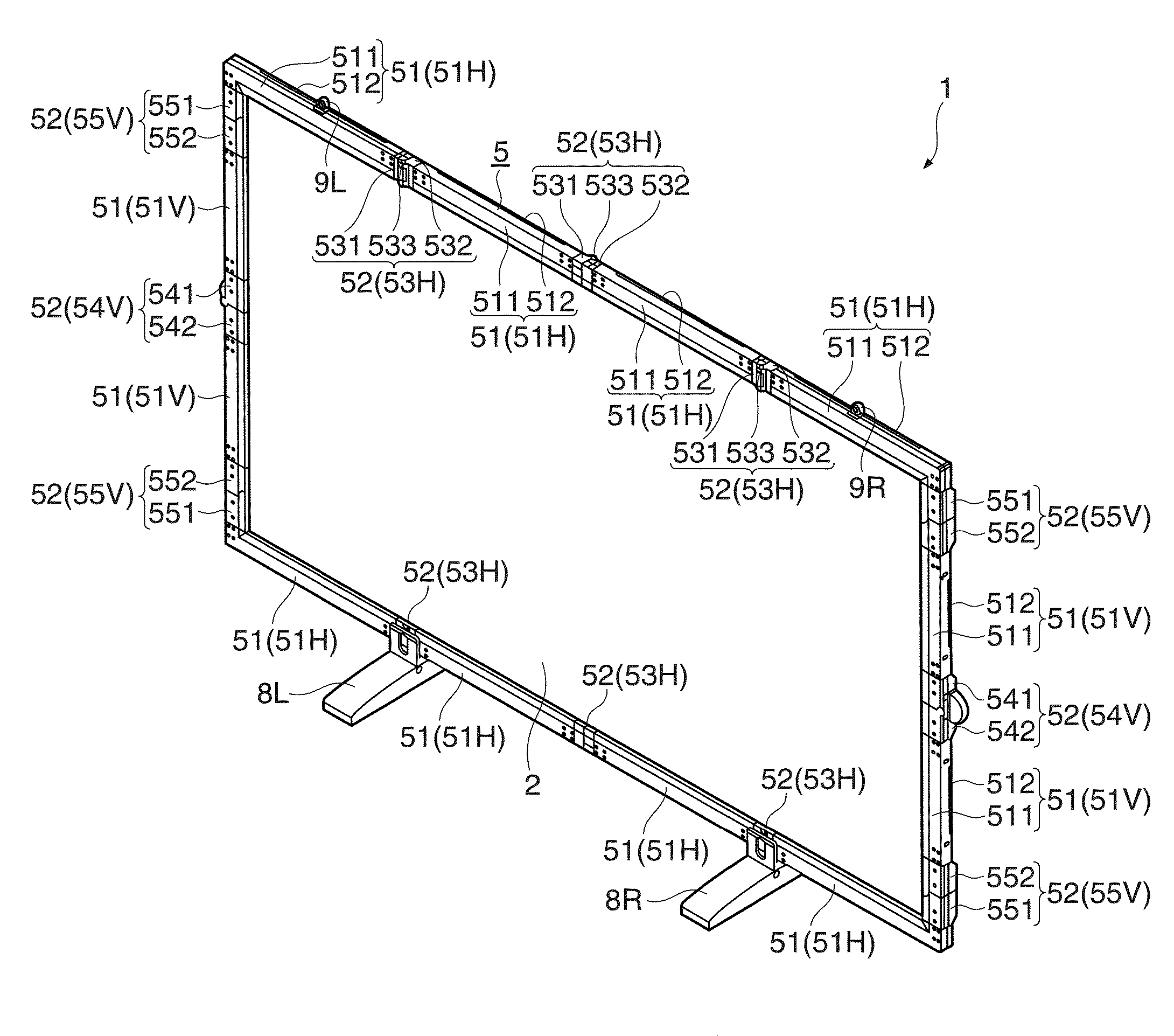
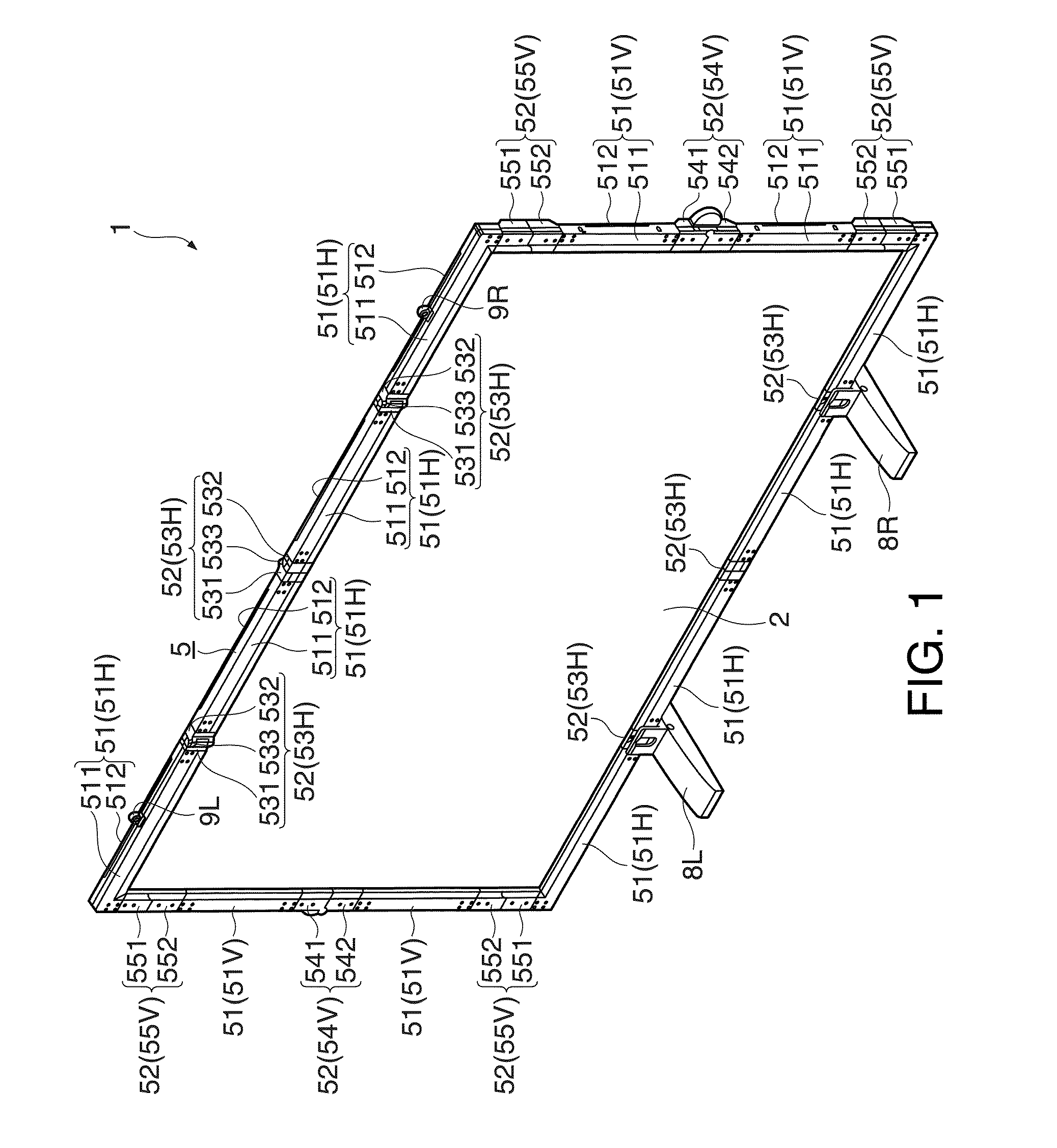
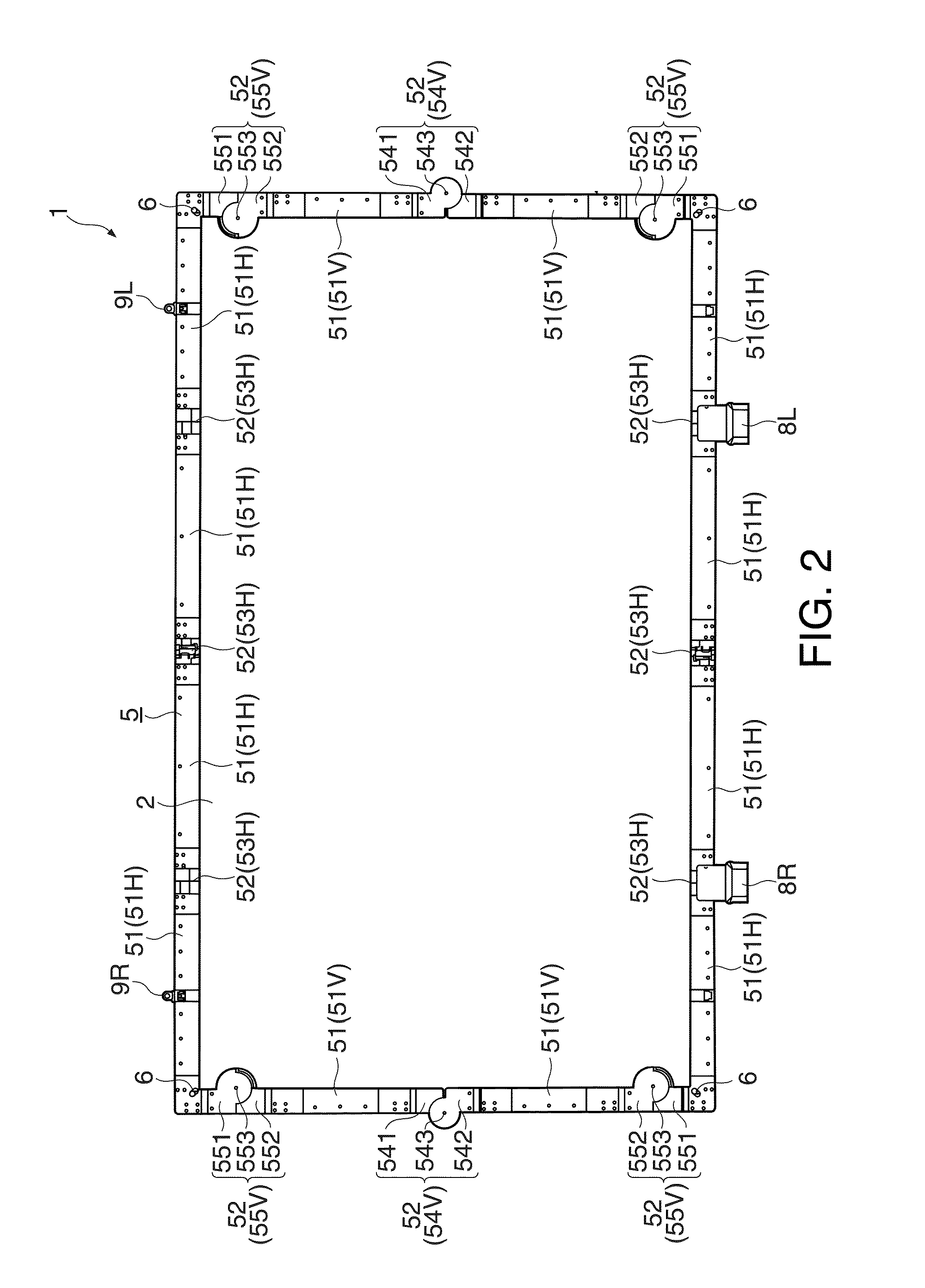
[0038]FIG. 1 and FIG. 2 are drawings showing schematic configurations of a screen 1. More specifically, FIG. 1 is a perspective view of the screen 1 in a state in which a projecting surface is formed when viewed from a front side. FIG. 2 is a perspective view of the screen 1 in the same state as in FIG. 1 when viewed from a back side.

[0039]In the following description, in the state in which the projecting surface of a screen cloth 2 is formed, the side of the projecting surface is referred to as a front surface, the opposite side from the projecting surface is referred to as a back surface, the right and left thereof when viewed from the front side are referred to as “right” and “left” for the sake of convenience.

[0040]On the screen 1, image light emitted, for example, from a projector or the like in an enlarged scale is projected. The screen 1 includes the screen cloth...


PUM


Abstract

A screen includes: a rectangular flexible screen cloth having which image light is projected; tubular portions provided along respective side edges of the screen cloth; an annular member inserted into the tubular portions; a frame member having a plurality of arm members connected so as to be capable of bending and stretching and assuming a rectangular frame shape in a state in which the plurality of arm members are extended; four hooking portions provided at four corners of the frame member and configured to hook the annular member to position the screen cloth in the frame of the frame member; and a tension applying mechanism provided on the frame member and configured to apply a tensile force to the screen cloth, at least two of the four hooking portions are provided movably inside and outside the frame member, the tension applying mechanism urges the at least two hooking portions outward the frame.

Description

[0001]The entire disclosure of Japanese Patent Application No. 2008-253784, filed Sep. 30, 2008, is expressly incorporated by reference herein.BACKGROUND[0002]1. Technical Field[0003]The present invention relates to a screen.[0004]2. Related Art[0005]In the related art, a folding-type screen improved in portability in the state of no-use is proposed as a screen on which image light emitted from a projector or the like in an enlarged scale is projected (for example, see International Publication WO02 / 097530).[0006]The folding-type screen disclosed in International Publication WO02 / 097530 employs a rectangular frame-type supporting frame configured to be foldable by hinges as a member for supporting a screen cloth.[0007]Then, the screen cloth is supported by the supporting frame by letting a plurality of cords through a plurality of holes formed on outer edge portions of the screen cloth and tying the plurality of cords to the supporting frame.[0008]However, with the screen disclosed ...

Claims


Application Information

Patent Timeline
Patent Type & Authority Applications(United States)
IPC IPC(8): G03B21/58H04N5/74
CPCG03B21/58
Inventor UNNO, TERUHIKOYUZAWA, FUMIOMARUYAMA, MASATO
Owner SEIKO EPSON CORP
Why Eureka
Try Eureka