Seal material

a technology of sealing material and sealing surface, which is applied in the direction of engine seals, mechanical equipment, engine components, etc., can solve the problems of increasing the size of the apparatus, requiring a large amount of load to tighten the seal, and disadvantageous anchoring fixation, so as to achieve the effect of easy separation and easy separation from the second member

Active Publication Date: 2016-09-20
VALQUA LTD
View PDF40 Cites 12 Cited by
  • Summary
  • Abstract
  • Description
  • Claims
  • Application Information

AI Technical Summary

Benefits of technology

[0011]By the above configuration, the seal can be easily separated from the second member (that is, a matching sealing surface) at a section in which an area of a contact surface is smaller for the sealing part as a starting point.
[0013]As described above, the present invention can be suitably and preferably applied to a lip sealing. More specifically, a step portion in which an area of a contact surface is smaller for the sealing part is formed on the surface of the leading end side of the lip part. Consequently, the seal can be easily separated from the second member at the step portion as a starting point.
[0015]In the case in which the step portion is formed in such a manner that a curved line is drawn in a wavelike fashion as described above, an area of a contact surface with the second member for the sealing part is varied uniformly in general at a generally constant interval in releasing a sealing. Consequently, a fixing force is also varied uniformly in general, and the seal material can be easily separated from the second member.
[0019]In the case in which the seal is formed in such a manner that a height of the seal is uneven in a circumferential direction as described above, a degree of a pressure contact of the second member and the seal is varied in a circumferential direction, whereby a fixing strength is varied in a circumferential direction. Consequently, the seal can be separated from the second member more easily at the position in which a fixing strength is smaller in a circumferential direction as a starting point.
[0020]By the seal in accordance with the present invention, a sealing property can be satisfactorily maintained in the state in which the seal material is tightened.

Problems solved by technology

At that time, an anchoring fixation may occur between a seal and a matching sealing surface disadvantageously.
In the case in which a metal seal is used in order to avoid the problem of the anchoring fixation, a great deal of load is required for tightening the seal material and it is necessary to increase the size of the apparatus.

Method used


Image

  • Seal material
  • Seal material
  • Seal material

Examples


Embodiment Construction

[0030]A seal in accordance with the present invention will be described below in detail with reference to the drawings.

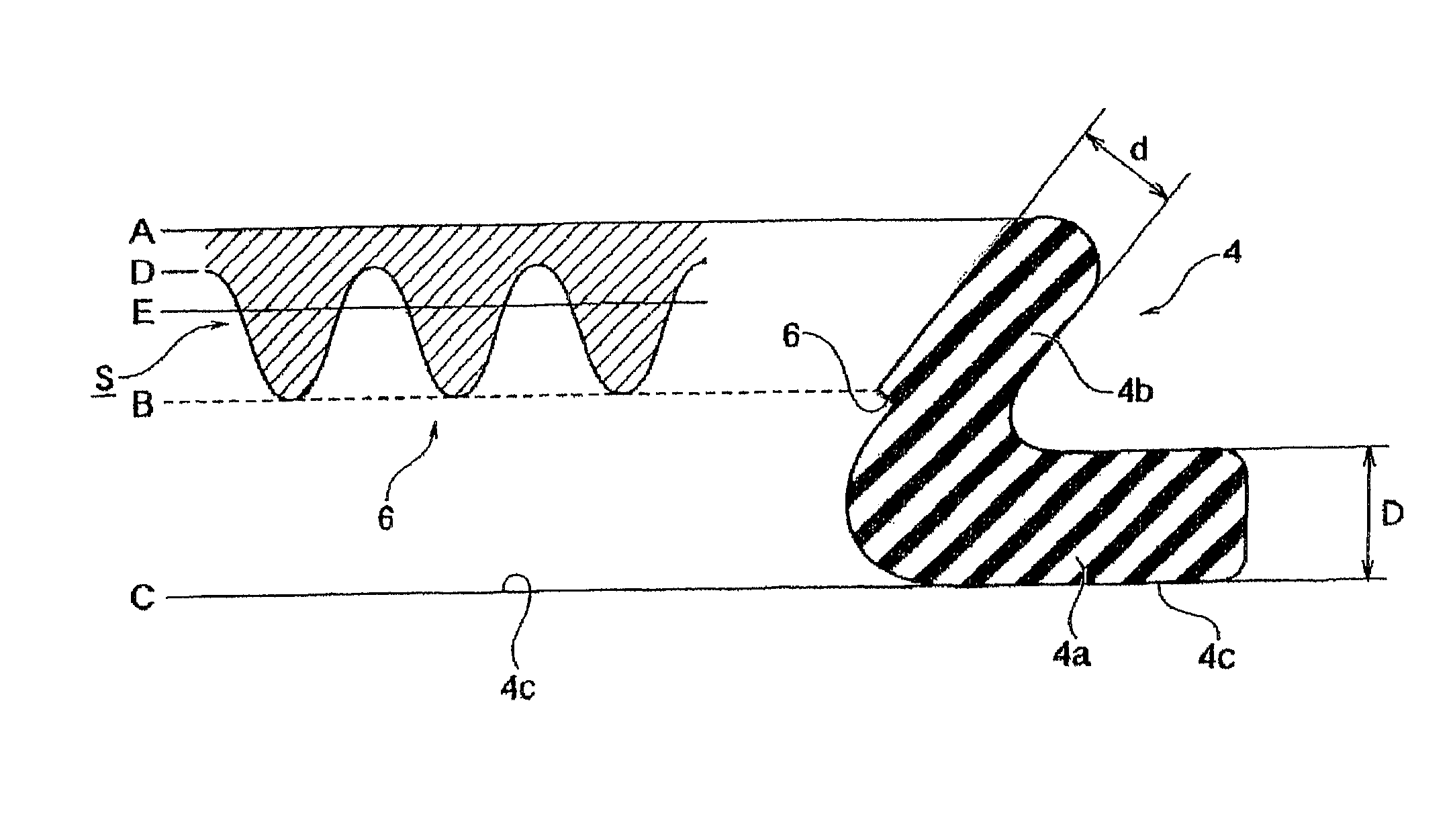
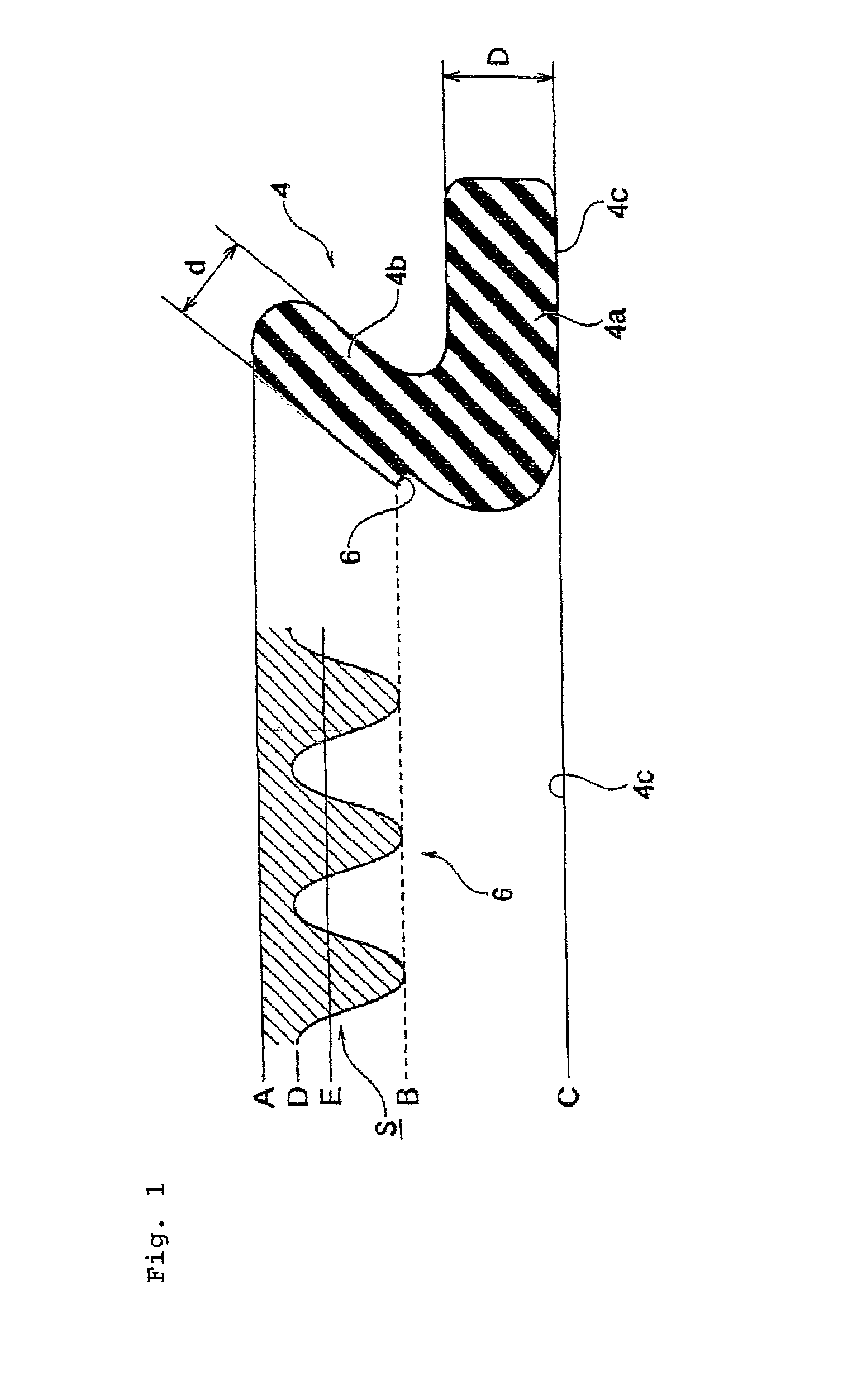
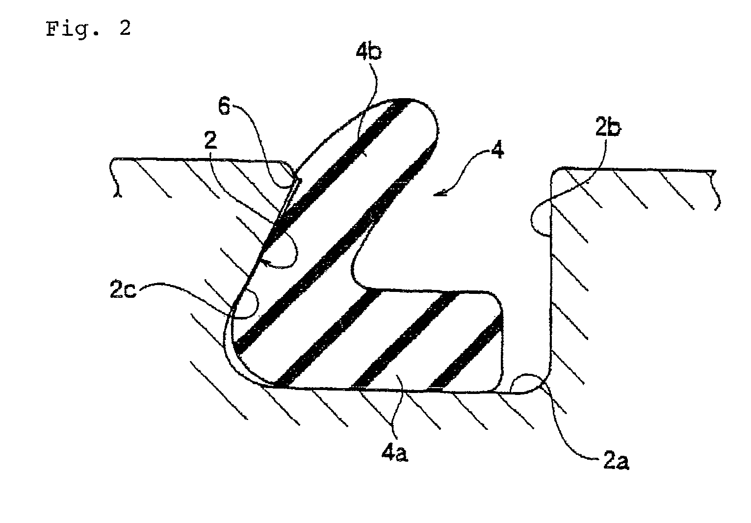
[0031]FIG. 1 shows a seal 4 in accordance with an embodiment of the present invention. FIG. 2 is a cross-sectional view showing a partial dovetail groove 2 as a seal groove in which the seal 4 of FIG. 1 is mounted in particular.

[0032]The partial dovetail groove 2 is formed in a coupling joint part of a semiconductor manufacturing apparatus such as a dry etching apparatus and a plasma CVD apparatus. A width of a bottom face 2a of a seal groove is larger than a width of an opening part of the partial dovetail groove 2. A wall surface 2b on a diameter inward side of the partial dovetail groove 2 is a vertical surface, and wall surface 2c on a diameter outward side of the partial dovetail groove 2 is an inclined face.

[0033]On the other hand, the seal 4 has a closed ring structure and is formed in a generally L shape in a cross section. The seal 4 is composed of a seal b...


PUM


Abstract

Provided is a seal that can ensure a satisfactory sealing property and can be easily separated from a sealing surface even in the case in which the seal is used for a long period of time under the conditions of a high temperature and a high pressure. The seal includes a seal body mounted in a seal groove that is formed in a first member and a second member is made to be in pressure contact with the first member to form a sealing part. The sealing part that comes into contact with the second member at the entire surface of the sealing part is formed along the entire circumference of the outer peripheral surface of the seal. A step portion is formed on the outer peripheral surface of the seal in such a manner that an area of a contact surface is smaller for the sealing part as the contact area is closer to the bottom side of the seal groove.

Description

TECHNICAL FIELD[0001]The present invention relates to a seal material.BACKGROUND ART[0002]A rubber seal material is extensively used as a general seal material that can easily ensure a sealing property by a low tightening force. For instance, a rubber seal material is used as a seal material for a semiconductor manufacturing apparatus or a gate valve for vacuum in a liquid crystal manufacturing apparatus.[0003]A rubber seal material is in a shape of an O ring or lip packing in a general way. In addition, seals having an irregular cross section that are disclosed in Patent documents 1 to 3 for instance are used in many cases.[0004]Patent document 1: Japanese Patent Application Laid-Open Publication No. 10-318373[0005]Patent document 2: Japanese Patent Publication No. 3050919[0006]Patent document 3: Japanese Patent Application Laid-Open Publication No. 2004-316724[0007]A high temperature processing is carried out for a semiconductor manufacturing apparatus in some cases. At that time,...

Claims


Application Information

Patent Timeline
Patent Type & Authority Patents(United States)
IPC IPC(8): F16J15/32F16J15/02F16J15/06
CPCF16J15/025F16J15/064
Inventor TSUJI, KAZUAKI
Owner VALQUA LTD
Why Eureka
Try Eureka