Al technical title is built by PatSnap Al team. It summarizes the technical point description of the patent document.
a modular, picture frame technology, applied in the field of picture frames and display frames or holders, to achieve the effect of convenient reconfiguration for mounting, secure retaining, and rapid change of conten
Inactive Publication Date: 2010-04-08
REIS RICHARD C
View PDF40 Cites 11 Cited by
Summary
Abstract
Description
Claims
Application Information
AI Technical Summary
This helps you quickly interpret patents by identifying the three key elements:
Problems solved by technology
Method used
Benefits of technology
[0016]To address these problems and to overcome the shortcomings of conventional picture frames, a configurable modular picture frame is provided. An object of the present invention is to provide an improved picture frame having the ability to rapidly change the content, readily reconfigure for mounting on vertical or horizontal surfaces, and reorient. A related object is to provide a picture frame having a quick connect and quick disconnect mechanism for inserting, securely retaining, and easily removing content with a minimum of effort. Accordingly, it is another object of the present invention to provide a picture frame which does not require the use of brads, nails, metal tabs, wedges, or clumsy clamps for holding content in place.
Problems solved by technology
Prefabricated subassemblies can use any mechanism of permanent attachment, but the individually separable components must have a mechanism of attachment that is neither permanent nor difficult to separate.
Method used
Image
Click on the blue label to locate the original text in one second.
Reading with bidirectional positioning of images and text.
Examples
examples
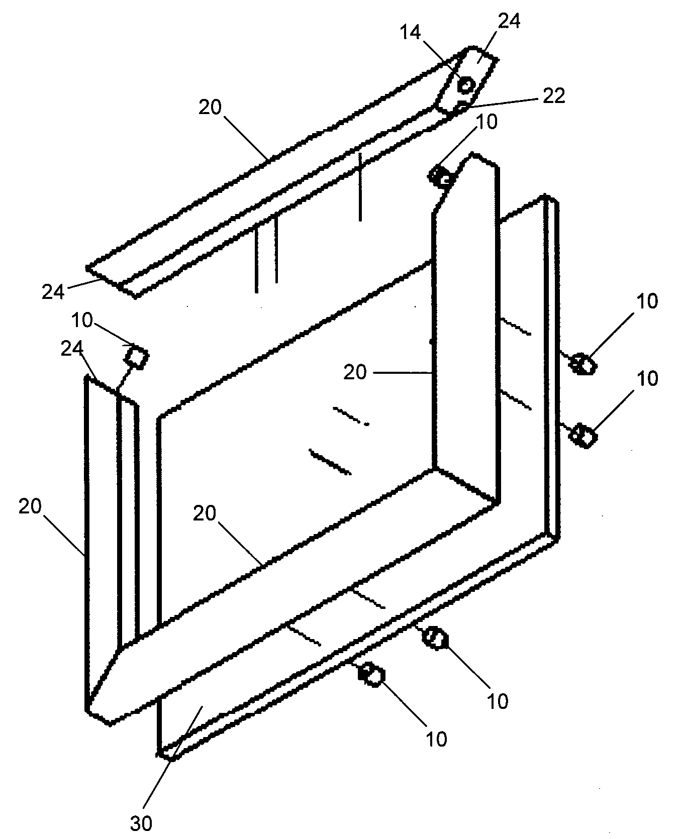
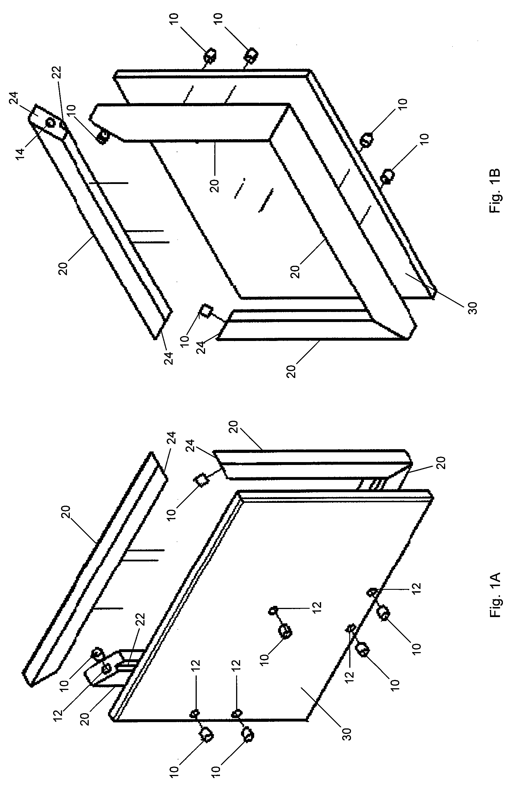
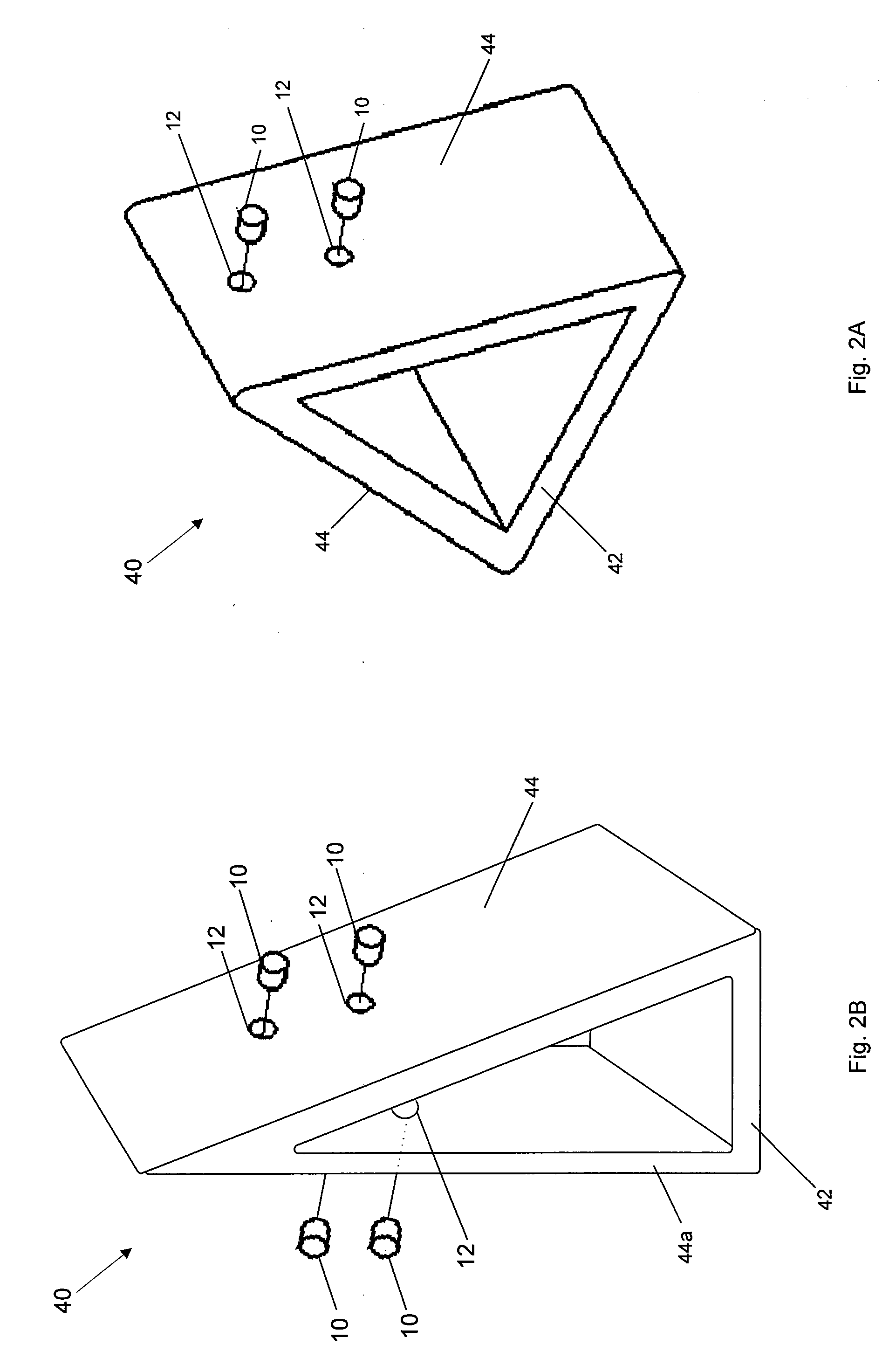
[0044]Referring now to the drawing, in which like reference numbers refer to like elements throughout the various figures that comprise the drawing, the figures display several, exemplary, basic components of the picture frame. The various non-attachment components of the picture frame can be made from many rigid or semi-rigid materials including, but not limited to, wood, plastic, metal, ceramics, rock, or composite materials. Multiple materials can be combined either within a component or alternatively individual components could be of a different material than other components. There are a large number of alternative combinations, because each individual component can be assembled by non-permanent attachment rather than preassembled into a permanently attached subassembly. The attachment mechanism can be any mechanism capable of securely attaching the components while still being detachable and reattachable, including magnets, hook-and-loop fasteners, or non-permanent adhesives.
[...
PUM
Property
Measurement
Unit
angle
aaaaa
aaaaa
sizes
aaaaa
aaaaa
sizes
aaaaa
aaaaa
Abstract
A picture frame for holding and displaying content. The picture frame has an edge with a channel receiving the content. An edge segment is attachable to and detachable from the remainder of the edge, using magnets, to allow insertion and removal of the content. A back has a front face to which the edge remainder is attached and a rear face including one or more magnets for attaching the back to a magnetically attractive surface. An optional stand has a plurality of elements that engage at least one of the back magnets to support the back in multiple directions and orientations. An optional hanger is made of a magnetically attracted material for engaging at least one of the back magnets and attach the hanger to the back. The hanger is configured to engage a fastener and hang the picture frame from the fastener when the stand is not in use.
Description
TECHNICAL FIELD[0001]The present invention relates generally to picture frames and display frames or holders and, more particularly, to picture frames and display frames or holders having components that are conveniently assembled and easily manufactured.BACKGROUND OF THE INVENTION[0002]The phrase “picture frame” is used in this document for convenience of description to refer to a picture or display frame or holder for holding and displaying virtually any type of substantially flat item (“content”). The content held and displayed in the picture frame may include a piece of artwork (e.g., prints, paintings, water colors, and drawings), photograph, citation, certificate, document, diploma, mirror, tapestry, poster, calendar, chart, restaurant menu, transportation timetable, leaflet, advertisement, and the like.[0003]Picture frames are well known in the art. Such frames usually include a main frame element having on three sides a channel into which are inserted, from the open end, fir...
Claims
Application Information
Patent Timeline
Application Date:The date an application was filed.
Publication Date:The date a patent or application was officially published.
First Publication Date:The earliest publication date of a patent with the same application number.
Issue Date:Publication date of the patent grant document.
PCT Entry Date:The Entry date of PCT National Phase.
Estimated Expiry Date:The statutory expiry date of a patent right according to the Patent Law, and it is the longest term of protection that the patent right can achieve without the termination of the patent right due to other reasons(Term extension factor has been taken into account ).
Invalid Date:Actual expiry date is based on effective date or publication date of legal transaction data of invalid patent.
Patent Type & Authority Applications(United States)