Fuel nozzle assembly for use with a gas turbine engine and method of assembling same

Inactive Publication Date: 2010-05-06
GENERAL ELECTRIC CO
View PDF7 Cites 6 Cited by
  • Summary
  • Abstract
  • Description
  • Claims
  • Application Information

AI Technical Summary

Problems solved by technology

The different temperatures may cause disparate thermal growths of the various tubular components, which may induce thermal strains.
A be

Method used


Image

  • Fuel nozzle assembly for use with a gas turbine engine and method of assembling same
  • Fuel nozzle assembly for use with a gas turbine engine and method of assembling same
  • Fuel nozzle assembly for use with a gas turbine engine and method of assembling same

Examples


Embodiment Construction

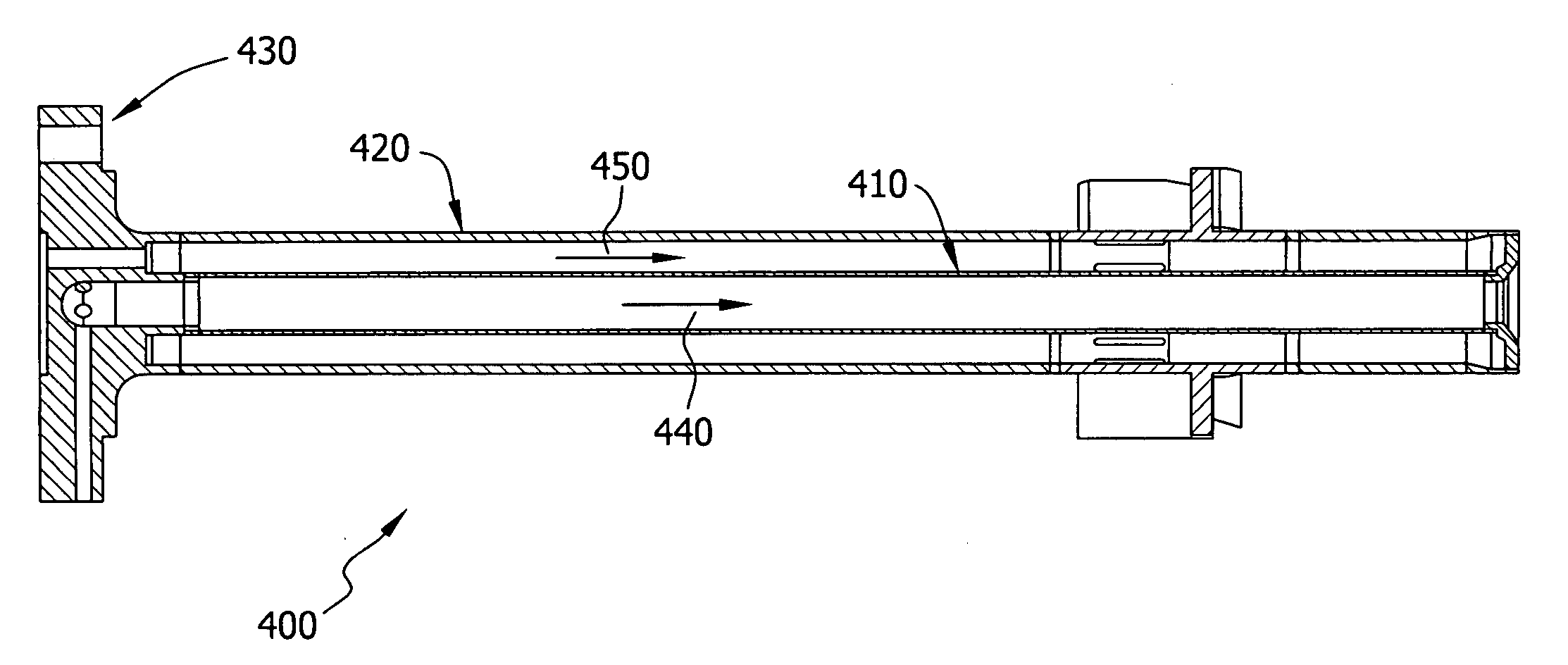
[0010]A fuel nozzle assembly with a simple and inexpensive alternative to a bellows assembly is desired. The present invention facilitates the relief of axial and radial thermal strains while limiting the number of parts and joints necessary to facilitate such relief.

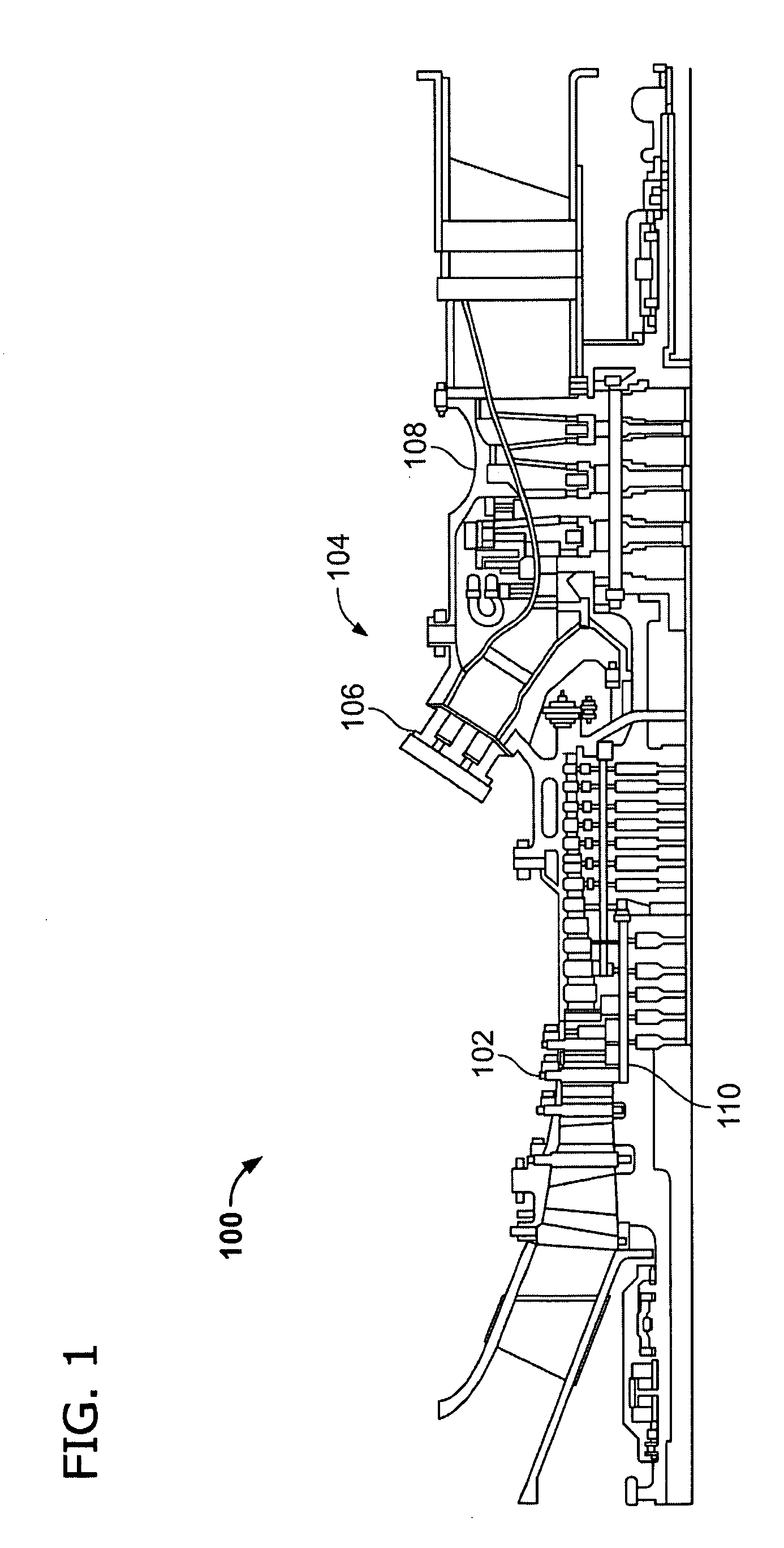
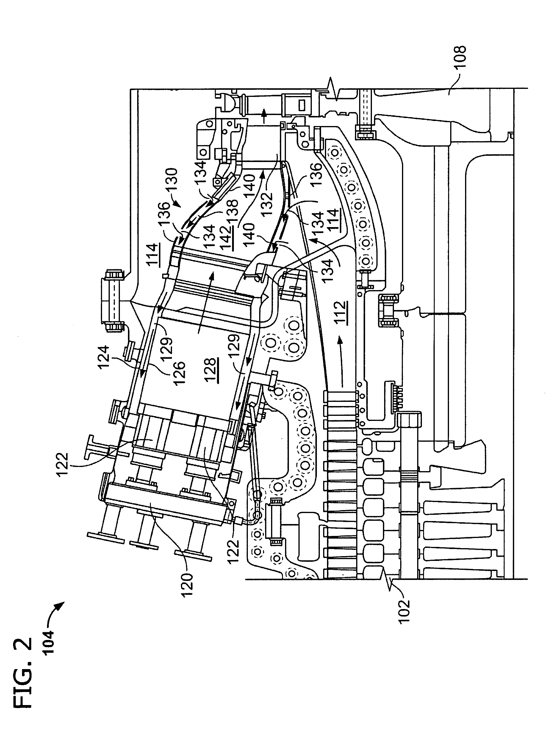
[0011]FIG. 1 is a schematic illustration of an exemplary gas turbine engine. Gas turbine engine 100 includes a compressor 102 and a combustor 104, which includes a fuel nozzle assembly 106. Gas turbine engine 100 also includes a turbine 108 and a common compressor / turbine shaft 110. In one embodiment, gas turbine engine 100 is a PG9371 9FBA Heavy Duty Gas Turbine Engine commercially available from General Electric Company, Greenville, S.C. Notably, the present invention is not limited to any one particular engine and may be used in connection with other gas turbine engines.

[0012]During operation, air flows through compressor 102 and compressed air is supplied to combustor 104 and, more specifically, to fuel nozzle assem...


PUM

PropertyMeasurementUnit
Coefficient of linear thermal expansionaaaaaaaaaa

Abstract

A fuel nozzle configured to channel fluid toward a combustion chamber within a gas turbine engine and a method for assembling the same are provided. The fuel nozzle includes a first hollow tube fabricated from a first material that has a first coefficient of thermal expansion and a second tube fabricated from a second material that has a second coefficient of thermal expansion that is different from the first coefficient of thermal expansion. The second tube is coupled within the first tube such that the first tube substantially circumscribes the second tube, and the second tube thermally expands approximately at a same rate as the first tube during fuel nozzle operation.

Description

BACKGROUND OF THE INVENTION[0001]The present invention relates generally to gas turbine engines and, more particularly, to fuel nozzle assemblies for use with gas turbine engines.[0002]At least some known fuel nozzle assemblies used with gas turbine engines include tubular components that define internal passages. The variety of fluids that may flow through the internal passages may cause each tubular component to operate at different temperatures. The different temperatures may cause disparate thermal growths of the various tubular components, which may induce thermal strains. To relieve such thermal strains, at least some known fuel nozzle assemblies include a bellows assembly that facilitates compensating disparate thermal growths. A bellows assembly, however, generally increases the cost and complexity of manufacturing, handling, and maintaining the gas turbine engine.BRIEF SUMMARY OF THE INVENTION[0003]In one embodiment, a method for assembling a fuel nozzle for use with a gas ...

Claims


Application Information

Patent Timeline
IPC IPC(8): F02C7/22B05B15/00F23R3/28
CPCF23D14/46F23D2206/10F23D2211/00F23R3/28Y10T29/49323F23R2900/00005F16L9/02F16L51/00F16L9/18F23D2212/20
Inventor MYERS, GEOFFREY D.SIMMONS, SCOTTTHOMAS, STEPHEN R.BAILEY, DONALD MARK
Owner GENERAL ELECTRIC CO
Why Eureka
Try Eureka