Three piece lift arm apparatus and method

Active Publication Date: 2010-05-06
CURBTENDER INC +1
View PDF31 Cites 3 Cited by
  • Summary
  • Abstract
  • Description
  • Claims
  • Application Information

AI Technical Summary

Benefits of technology

[0009]The present invention is a refuse truck lift arm with sections that are bolted, not welded, together. Where the sections are joined together

Problems solved by technology

Because welding tends to distort the metal being welded, it has often been difficult to produ

Method used


Image

  • Three piece lift arm apparatus and method
  • Three piece lift arm apparatus and method
  • Three piece lift arm apparatus and method

Examples


Embodiment Construction

[0021]The following description of the preferred embodiment(s) is merely exemplary in nature and is in no way intended to limit the invention, its application, or uses.

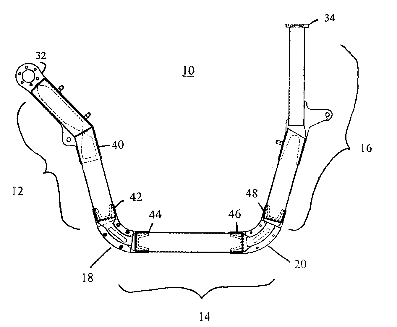
[0022]Referring now to the drawings wherein like reference numbers correspond to like elements, lifting arm 10 is comprised of three separate weldments, a proximate weldment 12, an intermediate weldment 14 and a distal weldment 16.

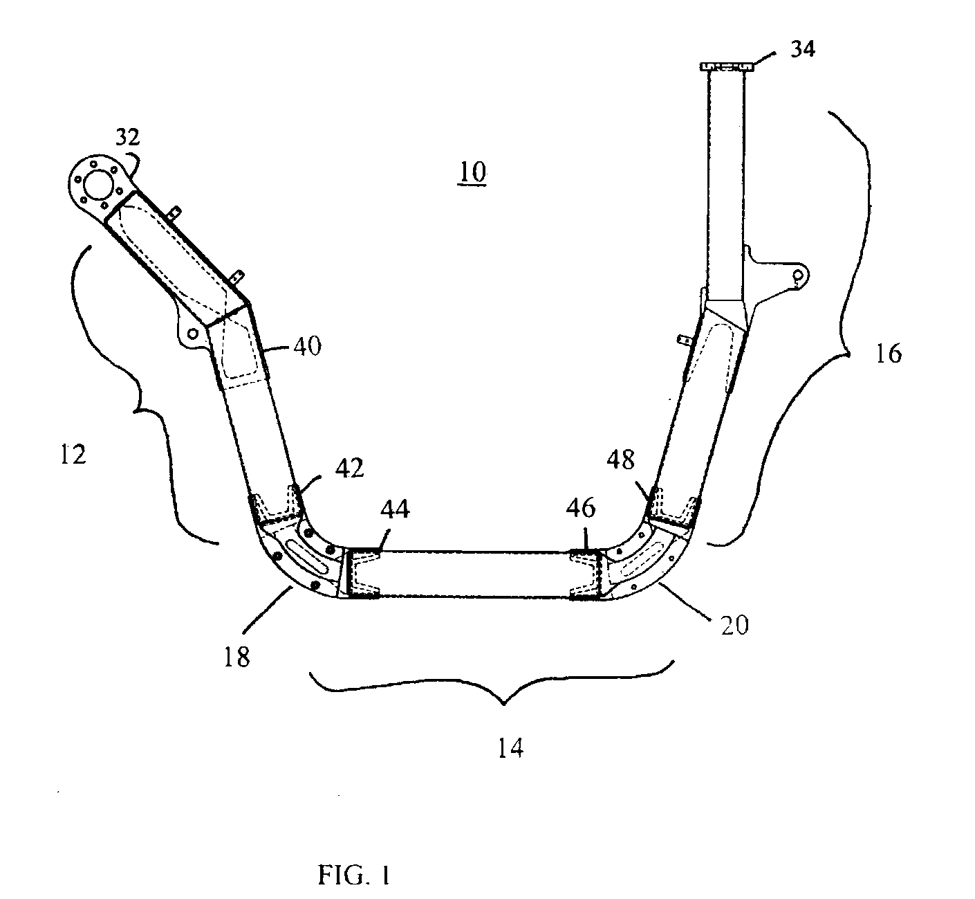
[0023]A joint 18 between the proximate weldment 12 and intermediate weldment 14 and a joint 20 between the intermediate weldment 14 and the distal weldment 16 are bolted, not welded together. Bolts and bolt holes 22 are used to assemble the weldments together into a completed lifting arm 10. Each joint, 18 and 20, is comprised of two plates 24. Each plate has an inner face 26 in which there is a recess 28. A corresponding inner face of a mating joint section from the other weldment being attached also has a recess. The recesses are dimensioned to seat a key 30. The depth of each recess 28 ad...


PUM

PropertyMeasurementUnit
Thicknessaaaaaaaaaa
Forceaaaaaaaaaa
Volumeaaaaaaaaaa

Abstract

The present invention is a refuse truck lift arm with sections that are bolted, not welded, together. Where the sections are joined together there is a recess and key arrangement. The key is seated in the recess of each half and straddles the inner face that divides them. In this way, shear forces that would otherwise be entirely borne by the bolts are also placed on the key. Each of the three sections, called “weldments,” are welded together in a novel way. The welding placement and sequence reduces welding distortion. Two C-shaped steel pieces are used for each straight section of each weldment. First, interior reinforcing brackets are welded into each C-section. Next, the two C-shaped sections are welded together, with the weld being between the edges that will form the thin side of the arm.

Description

CROSS-REFERENCE TO RELATED APPLICATIONS[0001]NoneSTATEMENT REGARDING FEDERALLY SPONSORED RESEARCH[0002]Not Applicable.APPENDIX[0003]Not Applicable.BACKGROUND OF THE INVENTION[0004]1. Field of the Invention[0005]The present invention is in the field of refuse truck lift arm fabrication and shipping thereof.[0006]2. Related Art[0007]The refuse industry has always used welding to assemble the lift arms on refuse trucks so that they are strong enough to lift dumpsters and the like. Traditionally, these arms were constructed of four flat pieces of steel whose edges were welded together to form the corners of a box; that is, a long arm piece with a rectangular cross section. The long pieces were then welded together, usually at an angle, to produce the familiar overhead lift arms. Because welding tends to distort the metal being welded, it has often been difficult to produce arms that are aligned properly.[0008]Refuse truck lift arms typically have two, three or more long sections that ar...

Claims


Application Information

Patent Timeline
IPC IPC(8): B65F3/04B23K9/00B65B5/00
CPCB65F3/041B65F2003/0279B21D53/88Y10T403/477Y10T29/49622Y10T29/49968Y10T29/49947
Inventor MEZERA, RICHARDWATJE, KEVINHALBUR, DOUGSTEEGE, DEAN
Owner CURBTENDER INC
Why Eureka
Try Eureka